
DCE-340 · Lesson 10 of 12 · 26 min
Testing and commissioning backup power
A backup power system is only as reliable as the evidence that it works. UPS units, batteries, generators, transfer switches and paralleling controls are complex, and their interactions during a real outage involve dozens of breakers, relays and control sequences operating within seconds. Many data centre outages have been traced to backup systems that had never been tested in the way they were eventually called upon to work. This lesson describes how backup power is tested: at the factory, during installation and start-up, in functional and integrated systems tests under load, and throughout its life, with the standards, instruments and acceptance criteria used at each stage.
The commissioning process
Commissioning verifies that a facility meets its design and the owner's requirements. For data centres it is usually organized in five levels, a convention widely used in the industry:
| Level | Name | What happens |
|---|---|---|
| 1 | Factory acceptance | Major equipment tested at the manufacturer, witnessed by the owner |
| 2 | Site inspection | Delivery, installation, labelling and connections checked against drawings |
| 3 | Pre-functional and start-up | Each component energized and started by the vendor; settings applied |
| 4 | Functional performance | Each system tested through all its modes, with load banks |
| 5 | Integrated systems test | The whole facility tested together, including utility failure, with simulated IT load |
A commissioning agent, independent of the contractor, writes test scripts from the design documents and sequences of operation, witnesses tests, records results and tracks issues to resolution. Tests are written with expected results, so that a pass or fail is clear, and every failure is retested after correction.
Factory acceptance tests
Testing major equipment at the factory finds problems when they are cheapest to fix. Typical factory tests include:
- UPS: efficiency at several loads, output voltage regulation and distortion with linear and non-linear loads, transient response to load steps, transfer to and from battery and bypass, parallel operation and load sharing for multi-module systems, and alarm and communication functions.
- Generators: load runs at 25%, 50%, 75% and 100% of rating, step-load response, voltage and frequency regulation, protective shutdowns, and governor and voltage regulator settings.
- Switchgear and paralleling controls: dielectric tests, control logic simulation with the actual programmable controllers, and breaker operation.
Witnessing tests in person or remotely lets the owner see equipment perform against the specification and approve it for shipping.
Batteries
Battery acceptance testing verifies capacity and the integrity of connections:
- Inspection and torque checks of every inter-cell connection, since a loose connection can melt under discharge current.
- Internal resistance (or impedance or conductance) measurements of every cell or block, establishing a baseline for later trending; outliers indicate defective cells.
- A capacity (discharge) test at a constant power or current to a defined end voltage, measuring whether the battery delivers its rated runtime, following IEEE 450 for vented lead-acid, IEEE 1188 for VRLA, or the manufacturer's procedures for lithium-ion.
Worked problem
Interpreting a capacity test
A battery rated for 10 minutes at 500 kW is discharged at 500 kW and reaches its end voltage after 8 minutes 45 seconds. The test temperature was 20 °C, and the rating is at 25 °C; the manufacturer gives a correction factor of 1.04 for 20 °C. What is its capacity as a percentage of rating?
Show solution
- Measured time: 8.75 min.
- Corrected to 25 °C: \(8.75 \times 1.04 = 9.1\) min.
- Capacity: \(9.1/10 = 91\%\).
Answer: About 91% of rated capacity. New batteries should test near 100% (some standards accept 90% for initial acceptance with improvement after cycling); many owners replace batteries when capacity falls to 80%, which is also the usual end-of-life definition (Lesson 3).
Load banks
Most backup power tests need load. Load banks are resistive (and sometimes reactive) loads that convert power to heat, rented or permanently installed:
- Large air-cooled load banks connected at switchgear test generators and UPS systems at full rating.
- Rack-mounted load banks in the white space simulate IT load, testing power and cooling together and showing how air and heat move.
- Liquid-cooled load banks connected to CDU loops simulate liquid-cooled AI racks (DCE-330).
- Reactive load banks test generators at their rated power factor (0.8), since a resistive load alone does not test the excitation system fully.
Load banks can be programmed to step and vary load, simulating the block loads and fluctuations of real IT equipment, including the fast swings of AI training (Lesson 4).
Generator testing
Generator tests verify rated output, transient performance and protective functions:
- Load run: the generator runs at rated load for several hours (often 4 hours or more at commissioning), recording voltage, frequency, temperatures, pressures and fuel consumption.
- Step-load test: the generator picks up load in the blocks expected in service, and the voltage and frequency dips and recovery times are compared with the specification, often based on ISO 8528-5 performance classes.
- Paralleling tests: synchronizing, load sharing between units, and load shedding and adding when a unit trips (Lesson 7).
- Protective functions: overspeed, low oil pressure, high temperature and others, tested by simulation.
import numpy as np

# Recorded generator response to a 0 to 60% block load step (synthetic data, 10 ms samples)
t = np.arange(0, 12, 0.01)
step = 1.0
f = 60.0 - np.where(t >= step, 5.2 * np.exp(-(t - step) / 0.9) * np.cos(2.2 * (t - step)), 0.0)
v = 480.0 - np.where(t >= step, 70.0 * np.exp(-(t - step) / 0.6), 0.0)

spec = {"freq_dip_pct": 10.0, "freq_band_pct": 1.0, "freq_recovery_s": 5.0,
        "volt_dip_pct": 20.0, "volt_band_pct": 2.0, "volt_recovery_s": 4.0}

def recovery_time(x, nominal, band_pct):
    outside = np.where(np.abs(x - nominal) > nominal * band_pct / 100)[0]
    return 0.0 if outside.size == 0 else t[outside[-1]] - step

f_dip = 100 * (60.0 - f.min()) / 60.0
v_dip = 100 * (480.0 - v.min()) / 480.0
f_rec = recovery_time(f, 60.0, spec["freq_band_pct"])
v_rec = recovery_time(v, 480.0, spec["volt_band_pct"])
checks = [("frequency dip", f_dip, spec["freq_dip_pct"], "%"), ("frequency recovery", f_rec, spec["freq_recovery_s"], "s"),
          ("voltage dip", v_dip, spec["volt_dip_pct"], "%"), ("voltage recovery", v_rec, spec["volt_recovery_s"], "s")]
for name, val, lim, unit in checks:
print(f"{name:18s}: {val:5.2f} {unit} (limit {lim} {unit}) {"PASS" if val <= lim else "FAIL"}")frequency dip : 8.67 % (limit 10.0 %) PASS frequency recovery: 1.72 s (limit 5.0 s) PASS voltage dip : 14.58 % (limit 20.0 %) PASS voltage recovery : 1.19 s (limit 4.0 s) PASS
Step-load results determine how much load can be transferred at once. If the generator cannot accept the whole facility in one step, the transfer sequence must stagger loads, for example by bringing on UPS rectifiers gradually (walk-in) and starting cooling equipment in stages.
In Canada, emergency generators for life-safety systems are installed and tested under CSA C282 (Emergency electrical power supply for buildings), which sets monthly and annual testing requirements; data centre generators that serve life-safety loads must meet it, and owners often apply similar regimes to standby generators.
UPS and transfer switch functional tests
Functional tests exercise each system through every mode and failure in its sequence of operation:
- UPS: loss of input (transfer to battery), return of input (rectifier walk-in), transfer to static bypass and back, manual maintenance bypass, module failure in a parallel system, battery runtime at load, and alarms to the monitoring system.
- Transfer switches: transfer on loss of normal source, retransfer on its return with the correct time delays, closed-transition retransfer where used, bypass-isolation operation, and in-phase monitoring.
- Power quality during transfers: recorded with fast power quality meters to verify that the IT load saw no interruption beyond what it tolerates.
Integrated systems testing
The integrated systems test (IST) is the final and most important test: the whole facility, power, cooling, controls and monitoring, operating together under simulated IT load, through the events it must survive. Typical scenarios:
- Utility failure ("pull the plug"): opening the utility main breakers with the facility at design load. The UPS carries the load, generators start, synchronize and close, transfer switches transfer, cooling restarts, and temperatures are watched.
- Utility return: retransfer to utility after a set period, with generators cooling down.
- Failures during the outage: a generator failing to start, a UPS module failing, a chiller tripping, with the redundancy expected to cover each.
- Maintenance scenarios: each concurrently maintainable component taken out of service while the facility runs.
- Controls failures: loss of a PLC, network switch or sensor.
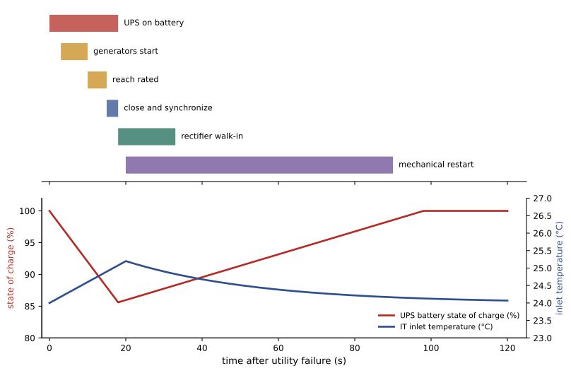
Worked problem
Time on battery during an IST
During an IST, generators close to the bus at 14 s and transfer switches transfer at 18 s; UPS rectifiers then walk in over 15 s, taking load back from the batteries linearly. How many seconds of full-load battery energy are used?
Show solution
- Full battery load until rectifiers start: 18 s.
- During walk-in, battery load falls linearly from 100% to 0% over 15 s: equivalent to 7.5 s at full load.
- Total: \(18 + 7.5 = 25.5\) s of full-load energy.
Answer: About 25 seconds, a small fraction of a 5- to 10-minute battery. The margin covers a generator that fails to start, the need to retry starting, or a slower paralleling sequence, which the IST also tests.
IST results often reveal issues that component tests cannot: a control sequence that waits for a signal no one programmed, a cooling restart that overloads the generators, a breaker whose settings trip on generator current. Finding these before the facility carries customer load is the purpose of the test.
Testing through the life of the facility
After commissioning, periodic testing keeps the system proven:
- Generators: monthly runs (often under load), annual load bank tests where real load is too light, fuel quality testing, and periodic tests of the full transfer sequence.
- Batteries: monthly visual checks and voltage readings, quarterly or continuous internal resistance monitoring, and capacity tests at intervals that shorten as batteries age.
- UPS: annual preventive maintenance, including transfer tests and thermography of connections.
- Transfer switches and switchgear: annual operation, cleaning, torque checks and protective relay testing; circuit breakers exercised so mechanisms do not stick.
- Periodic "pull the plug" tests: some operators repeat an actual utility-failure test once or twice a year, under real IT load, to prove the whole chain works; others consider the risk too high and rely on component tests. The choice is a balance between confidence and risk.
Each test is performed under a method of procedure (MOP) approved in advance, with back-out steps and communication to stakeholders, because testing itself carries risk.
Common mistakes
MistakeAccepting equipment without witnessing factory tests.
InsteadWitness factory acceptance tests and verify results against the specification.
MistakeTesting generators only with resistive load.
InsteadInclude reactive load and realistic load steps to test excitation and governors.
MistakeSkipping the integrated systems test to meet a schedule.
InsteadRun the IST; it finds the interaction problems that cause real outages.
MistakeTesting transfer sequences only at light load.
InsteadTest at design load with load banks, including failure scenarios.
MistakeRunning periodic tests without approved procedures.
InsteadUse MOPs with back-out plans and stakeholder communication.
Summary and key terms
- Commissioning runs from factory acceptance through site checks, start-up and functional tests to the integrated systems test.
- Batteries are checked by connection torque, internal resistance and capacity tests corrected for temperature.
- Load banks, resistive, reactive, rack and liquid, provide realistic loads.
- Generators are tested for load runs, step response, paralleling and protection.
- The IST exercises the whole facility through utility failure and other failures under load.
- Periodic testing under approved procedures keeps the system proven for its whole life.
- Commissioning
- Verifying that a facility meets its design and requirements.
- Commissioning agent
- An independent party who scripts and witnesses tests.
- Factory acceptance test
- Testing equipment at the manufacturer before shipping.
- Capacity test
- A controlled discharge measuring a battery's actual runtime.
- Load bank
- Equipment providing a controllable artificial load for testing.
- Step-load test
- Applying load in blocks to measure transient response.
- Integrated systems test
- A test of the whole facility working together under load.
- Walk-in
- Gradual ramping of a rectifier's load after power returns.
- Pull-the-plug test
- A deliberate utility disconnection to test backup systems.
- MOP
- Method of procedure for work on critical systems.
Practice problems
Work each problem on paper first, then reveal the answer to check.
What are the five commissioning levels?
Show answer
Factory acceptance, site inspection, start-up, functional tests, integrated systems test.
Capacity of a battery giving 7.6 min against a 10 min rating, correction 1.05?
Show answer
80%.
Why test generators with reactive load?
Show answer
To exercise the excitation system at rated power factor.
What does a step-load test measure?
Show answer
Voltage and frequency dips and recovery times.
Frequency dip from 60 Hz to 55.2 Hz in percent?
Show answer
8%.
What standard governs emergency generator testing in Canada? In the US?
Show answer
CSA C282; NFPA 110.
What does the IST reveal that component tests cannot?
Show answer
Interactions between systems, controls and sequences.
Full-load battery seconds for 20 s plus a 10 s linear walk-in?
Show answer
25 s.
Why exercise circuit breakers periodically?
Show answer
So their mechanisms do not stick.
What must accompany every periodic test of critical systems?
Show answer
An approved method of procedure.
Lesson quiz · 5 questions
Score 60% or more to complete this lesson.
Create a free account to save your progress, take quizzes and earn a certificate.