
CSCO-112 · Lesson 3 of 12 · 18 min
Switching and VLAN concepts
▶ Video coming soon A video version of this lesson is on the way.
The old Prairie Paws switch was unmanaged: plug anything into any port and it worked. That simplicity was also its weakness. The reception PCs, the phones, the exam-room tablets and the free guest Wi-Fi in the waiting room all shared one network, so a visitor's phone in the waiting room could see the clinic's practice-management server. Dev's plan for the new switch separates them. "Same switch, same cables," he tells Jordan, "but four networks that can't see each other unless the router lets them." The tool that makes this possible is the VLAN, and understanding it starts with how a switch forwards frames.
How a switch forwards frames
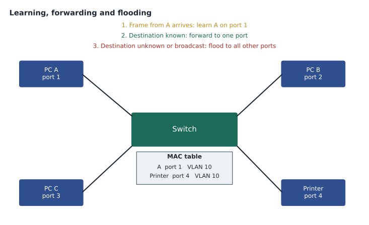
A switch works at layer 2 of the OSI model. It forwards Ethernet frames based on their destination MAC address, the hardware address built into every network interface. To do this, it builds a MAC address table, also called a CAM table, that records which MAC address was last seen on which port. Each time a frame arrives, the switch reads the frame's source MAC address and notes the port it came in on. This is called learning.
To forward the frame, the switch looks up the destination MAC address in the table. If it finds the address, it sends the frame out of that one port only, which is called forwarding or filtering. If the address is not in the table, the switch sends the frame out of every port except the one it arrived on, which is called flooding. Broadcast frames, addressed to FF:FF:FF:FF:FF:FF, are always flooded, because they are meant for every device on the network. Entries in the table age out after a few minutes of silence, typically five, so the table keeps up as devices move.
SW-PP1# show mac address-table dynamic
          Mac Address Table
-------------------------------------------
Vlan    Mac Address       Type        Ports
----    -----------       --------    -----
  10    0050.56a1.3c10    DYNAMIC     Gi1/0/1
  10    0050.56a1.7d22    DYNAMIC     Gi1/0/3
  20    00a3.8e41.0b5f    DYNAMIC     Gi1/0/2
  99    0c75.bd12.4401    DYNAMIC     Gi1/0/24
Total Mac Addresses for this criterion: 4
Because a switch sends unicast frames only where they need to go, each port is its own collision domain, and modern full-duplex links have no collisions at all. A switch does not, however, stop broadcasts: every device in the same layer 2 network hears every broadcast. That whole group is a broadcast domain. In a flat network with one broadcast domain, every ARP request, every DHCP discovery and every chatty device's announcements reach every other device. Routers stop broadcasts, and so do VLANs.
What a VLAN is
A virtual LAN (VLAN) divides one physical switch, or a group of connected switches, into several separate layer 2 networks. Each VLAN is its own broadcast domain. Devices in VLAN 10 can talk directly to each other, but a frame from VLAN 10 is never forwarded into VLAN 20 by the switch. To get from one VLAN to another, traffic has to go through a router or a layer 3 switch, which is where access rules can be applied. In practice each VLAN is also given its own IP subnet.
VLANs are used for security, for performance and for organization. Keeping guest Wi-Fi on its own VLAN stops visitors from reaching business systems. Putting phones on a voice VLAN lets the network give their traffic priority. Grouping devices by function rather than by where they are plugged in means a reception PC in the branch clinic can be in the same VLAN as one in the main clinic. Dev's design for Prairie Paws uses four VLANs.
| VLAN | Name | Subnet | Devices |
|---|---|---|---|
| 10 | Staff | 10.20.10.0/24 | Reception and exam-room PCs, the practice-management server, printers |
| 20 | Voice | 10.20.20.0/24 | Desk phones |
| 30 | Guest | 10.20.30.0/24 | Waiting-room Wi-Fi |
| 99 | Management | 10.20.99.0/24 | The switch, the access points and the firewall management interfaces |
Every switch port starts in VLAN 1, the default VLAN. Leaving devices in VLAN 1 is common in small networks but considered poor practice, because VLAN 1 also carries some of the switch's own control traffic and is the first place an attacker looks. Brightline's standard is to leave VLAN 1 unused, move unused ports to an unused VLAN and shut them down.
Access ports and trunk ports
A switch port is usually either an access port or a trunk port. An access port belongs to one VLAN and connects an end device such as a PC or a printer. The device has no idea VLANs exist; it sends and receives ordinary frames, and the switch keeps track of which VLAN they belong to. A trunk port carries traffic for many VLANs over one link, typically between two switches, between a switch and a router, or to a wireless access point that serves several SSIDs.
On a trunk, the switch has to mark each frame with its VLAN so that the device at the other end knows where it belongs. The standard way to do this is IEEE 802.1Q tagging, which inserts a small 4-byte tag into the Ethernet frame containing a 12-bit VLAN ID. Twelve bits allow VLAN IDs from 1 to 4094 (0 and 4095 are reserved). The tag is added when a frame leaves on a trunk and removed when it leaves on an access port, so end devices never see it.
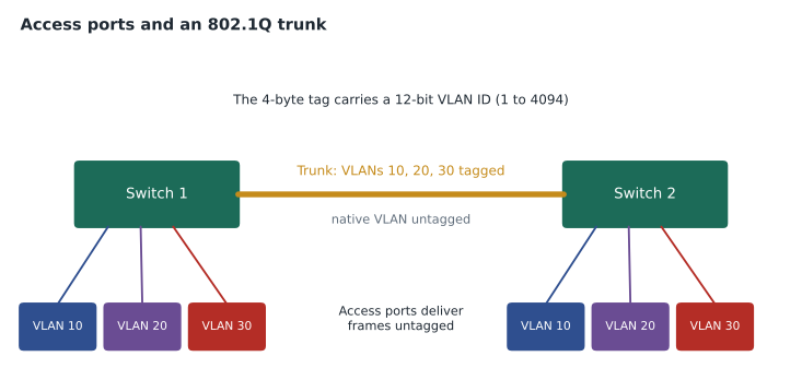
One VLAN on each trunk is the native VLAN, whose frames cross the trunk without a tag. By default it is VLAN 1. Both ends of a trunk must agree on the native VLAN; if they do not, frames leak from one VLAN into another and the switches log a native VLAN mismatch. Many organizations change the native VLAN to an otherwise unused VLAN for security. Trunks can also be limited to only the VLANs they need with an allowed VLAN list, which keeps unnecessary broadcasts off links.
SW-PP1(config)# vlan 10
SW-PP1(config-vlan)# name Staff
SW-PP1(config-vlan)# vlan 20
SW-PP1(config-vlan)# name Voice
SW-PP1(config-vlan)# exit
SW-PP1(config)# interface gigabitEthernet1/0/1
SW-PP1(config-if)# description Reception-PC1
SW-PP1(config-if)# switchport mode access
SW-PP1(config-if)# switchport access vlan 10
SW-PP1(config-if)# exit
SW-PP1(config)# interface gigabitEthernet1/0/24
SW-PP1(config-if)# description Uplink-R-PP1
SW-PP1(config-if)# switchport mode trunk
SW-PP1(config-if)# switchport trunk allowed vlan 10,20,30,99
Voice VLANs and Power over Ethernet
An IP phone on a desk usually has a small switch built in, so one cable from the wall feeds the phone and a second short cable runs from the phone to the PC. The switch port then needs to carry two kinds of traffic: the PC's data and the phone's voice. Cisco switches handle this with a voice VLAN: the port is an access port in the data VLAN, with a second VLAN set for voice. The phone learns the voice VLAN from the switch and tags its own traffic, while the PC's traffic travels untagged in the data VLAN. Voice traffic can then be marked for priority, so calls stay clear when the network is busy.
Phones, access points and cameras often take their power from the switch through Power over Ethernet (PoE). The switch checks whether a connected device can accept power before supplying it, so plugging an ordinary PC into a PoE port is safe. Each PoE switch has a total power budget, and a switch full of cameras and access points can run out. When that happens, low-priority ports lose power, and a device that keeps rebooting is a classic sign. The show power inline command shows how much power each port is drawing and how much budget remains.
Getting traffic between VLANs
Because VLANs are separate broadcast domains, a PC in VLAN 10 cannot reach the printer in VLAN 30 without a router. Inter-VLAN routing can be done in three ways. The oldest uses one router interface per VLAN, which wastes ports. The common small-network design, called router on a stick, uses one trunk link to the router, with a subinterface for each VLAN that acts as that VLAN's default gateway. Larger networks use a layer 3 switch, which routes between VLANs internally using SVIs, much faster than sending traffic out to a router and back.
At Prairie Paws, the switch trunks to the router R-PP1, which has subinterfaces for VLANs 10, 20, 30 and 99. Each PC's default gateway is the router's subinterface address in its VLAN, such as 10.20.10.1. The firewall rules on the router allow staff to reach the internet and the practice-management server, allow phones to reach the cloud phone system, and allow guests to reach only the internet. That design is why a visitor's phone can no longer see the server.
Loops and Spanning Tree
Redundant links between switches are good for reliability, but at layer 2 they create a danger. Ethernet frames carry no hop limit, so a broadcast sent into a loop circles forever, multiplying each time it is flooded. Within seconds a broadcast storm can saturate every link and freeze the network. The MAC address table also becomes unstable, as the same address appears to move between ports many times a second.
Switches prevent this with the Spanning Tree Protocol (STP), defined in IEEE 802.1D and improved in Rapid STP (802.1w). The switches exchange messages, elect a root bridge and then block just enough ports to leave one loop-free path between any two points. If an active link fails, a blocked port takes over. A CCST technician does not need to configure STP, but should recognize its effects: a port that is blocking is not a fault, and a cable plugged between two wall jacks by a curious visitor can create a loop that STP has to catch. Features such as BPDU guard shut down an access port automatically if a switch appears where only a PC should be.
Common mistakes
MistakeAssuming that devices on the same switch can always talk to each other.
InsteadCheck the VLANs; devices in different VLANs need a router or layer 3 switch between them.
MistakePlugging an access point that serves several SSIDs into an access port.
InsteadUse a trunk that carries each SSID's VLAN, or the extra networks will not work.
MistakeMismatching the native VLAN at the two ends of a trunk.
InsteadSet the same native VLAN on both ends and limit the allowed VLAN list.
MistakeTreating a blocked spanning-tree port as a broken link.
InsteadA blocking port is STP preventing a loop; check show spanning-tree before changing anything.
VLANs across several switches
Larger sites have several switches, and a VLAN can span all of them as long as the trunks between them carry it. A staff PC on the second floor and a server in the basement can both be in VLAN 10, linked by trunks through the switches in between. Each switch must know the VLAN exists; if a trunk's allowed list leaves out VLAN 10, or a switch has never had VLAN 10 created, the PC and the server cannot reach each other even though both ports look correct. show interfaces trunk lists, for each trunk, the VLANs allowed and the VLANs actually active, which makes a missing VLAN easy to spot.
Worked problem
Why the new printer will not print
After the switch replacement, the new label printer is plugged into port Gi1/0/12. It gets an address in 10.20.30.0/24, and reception PCs in 10.20.10.0/24 cannot print to it. What is the likely cause and fix?
Show solution
- 10.20.30.0/24 is the guest subnet, so the printer is in VLAN 30.
- The firewall rules allow guests only to reach the internet, and staff PCs are not allowed into the guest VLAN.
- Gi1/0/12 was probably left in the wrong VLAN; show vlan brief or show interfaces status would show VLAN 30 on that port.
Answer: Set Gi1/0/12 as an access port in VLAN 10, then renew the printer's address so it moves to the staff subnet.
Summary and key terms
- Switches learn source MAC addresses into a MAC address table, forward known unicast frames to one port and flood broadcasts and unknown destinations.
- A VLAN splits a switch into separate broadcast domains, each normally with its own subnet.
- Access ports carry one VLAN untagged to end devices; trunks carry many VLANs using 802.1Q tags, with one untagged native VLAN that must match at both ends.
- Voice VLANs separate phone traffic, and PoE powers phones and access points within the switch's budget.
- Traffic between VLANs needs a router or layer 3 switch, and Spanning Tree blocks redundant links to stop loops.
- MAC address table
- The switch table that maps MAC addresses to ports and VLANs.
- Flooding
- Sending a frame out of every port except the one it came in on.
- Broadcast domain
- The set of devices that receive each other's broadcasts.
- VLAN
- A virtual LAN, a separate layer 2 network on shared switches.
- Access port
- A switch port in one VLAN, for an end device.
- Trunk port
- A link carrying several VLANs, with 802.1Q tags.
- Native VLAN
- The VLAN whose frames cross a trunk untagged.
- Spanning Tree Protocol
- A protocol that blocks redundant switch links to prevent loops.
Practice problems
Work each problem on paper first, then reveal the answer to check.
A switch receives a frame for a MAC address that is not in its table. What does it do?
Show answer
It floods the frame out of every port in that VLAN except the one it arrived on.
How many bits does 802.1Q use for the VLAN ID, and what is the highest usable ID?
Show answer
12 bits; 4094.
Why does a PC in VLAN 10 need a router to reach a server in VLAN 20?
Show answer
Each VLAN is a separate broadcast domain and subnet, so traffic between them must be routed.
Lesson quiz · 5 questions
Score 60% or more to complete this lesson.
Create a free account to save your progress, take quizzes and earn a certificate.