
BAS-420 · Lesson 9 of 12 · 22 min
Unstable loops and hunting
▶ Video coming soon A video version of this lesson is on the way.
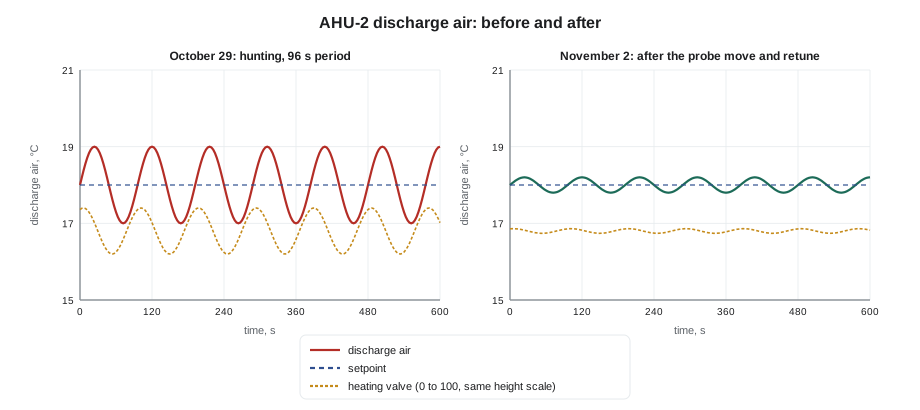
The ninth tab of the trouble file holds the printout that started this course: Tilden AHU-2's discharge air temperature on Thursday, October 29, swinging between 17 and 19 °C (62.6 and 66.2 °F) every 96 seconds, with the heating valve swinging between 20 and 40 in step with it. Behind it is the rest of the story. In September, someone had raised the loop's gain from 2 to 8 per K (4.4 per °F) and cut its integral time from 90 to 30 seconds to get a faster warm-up. The discharge air probe sat 0.6 m (2 ft) after the coil, in air that had not yet mixed. On Friday, October 30, at 7:00, Prakash moved the probe downstream of the supply fan, ran a step test and retuned the loop. By Monday, November 2, the trend held within ±0.2 K (±0.4 °F). "Two causes," Prakash said. "Somebody tuned it too hot, and the sensor made it worse. If we had only fixed one, it would have come back."
This lesson covers loops that hunt, cycle or never settle: how to recognise them, how to tell a tuning problem from a mechanical or interaction problem, and how to fix them without making the next problem. It assumes the loop and tuning knowledge from BAS-130.
What hunting is and why it matters
A loop hunts when its process variable and output keep oscillating around setpoint instead of settling. The oscillation may be steady, growing or slowly dying away. Some loops cycle by design, such as a two-position fan coil switching on and off around a differential, and that is not hunting. Hunting is an oscillation the loop should not have.
Hunting costs three ways. It wears out actuators, valves, dampers, drives and compressors. It makes people uncomfortable, especially when it swings air temperature, as the lecture wing occupants felt as drafts. And it wastes energy, because a loop that swings heating and cooling or speeds a fan up and down uses more energy than a steady one.
Worked problem
How much a hunting valve travels
AHU-2's heating valve swung between 20 and 40 open every 96 seconds. How many oscillations is that per hour, how much valve travel, and how many full strokes is that equivalent to over a 10-hour occupied day?
Show solution
- Cycles per hour: 3,600 ÷ 96 = 37.5.
- Each cycle moves the valve from 20 to 40 and back: 20 + 20 = 40 points of travel.
- Travel per hour: 37.5 × 40 = 1,500 points, which is 1,500 ÷ 100 = 15 full strokes.
- Over a 10-hour day: 15 × 10 = 150 full strokes.
Answer: About 37.5 cycles and 15 full strokes per hour, or about 150 full strokes in a day. A valve and actuator in steady service might travel a few full strokes a day, so hunting can use up years of actuator life in months.
Recognising the type of oscillation
A fast trend of the setpoint, process variable and output on one chart is the starting point, as in lesson 2. Read three things from it: the period (time from one peak to the next), the amplitude of the process variable and of the output, and the shape of each.
| What the trend shows | Most likely cause | Next step |
|---|---|---|
| Smooth sine-like swings in both output and process variable, period a few times the loop's dead time | Gain too high or integral too fast | Step test and retune |
| Output ramps slowly up and down in a sawtooth; process variable jumps in steps | Stiction or backlash in the actuator, valve or damper (sticky device) | Watch the device; check linkage, packing and actuator size |
| Slow, large swings, period many times the dead time | Integral too slow with gain too high, or interaction with a slower loop | Put the loop in manual and see whether the swing continues |
| Oscillation continues with the loop in manual | Something outside the loop: another loop, a cycling stage, a disturbance | Find what else cycles at the same period |
| Oscillation only at low or high load | The process gain changes with load (nonlinear valve, oversized valve, low flow) | Tune at the worst-case load or use gain scheduling |
| Noisy process variable with a jittery output | Electrical noise or turbulence at the sensor | Fix the noise source; use only a small input filter |
Two tests separate the families. The first is to put the loop in manual, holding its output steady, and watch the process variable. If the swinging stops, the loop itself is causing it, through its tuning or through a sticky device it drives. If the swinging continues, something else is driving it, and retuning this loop will not help. The second is to watch the final device while the loop runs. A valve stem or damper shaft that moves in jerks while the output ramps smoothly is sticking, and no amount of tuning will make it behave well.
Tuning that is too aggressive
The most common cause of hunting is tuning that is too aggressive for the process. Gain too high makes the loop over-react; integral time too short makes it keep pushing after the process has started to respond. Dead time, the delay before the process variable starts to respond to a change in output, makes both worse: the loop keeps changing its output during the dead time because it has not seen any result yet.
Aggressive tuning often comes from a well-meant change. Someone wants a faster warm-up, or a loop that reacts quicker to a complaint, and raises the gain. The loop is fine at the time of the change, in one set of conditions, and hunts later in another. That is why the audit trail and change log are part of every loop investigation. AHU-2's September change was in the log.
Retuning starts with a measurement of the process, not with guessing. The step test from BAS-130 puts the loop in manual, makes a step change in the output, and records how far and how fast the process variable moves: the process gain, the dead time and the time constant. Lambda tuning then sets the gain and integral time from those numbers and a chosen closed-loop response time, lambda. A longer lambda gives a gentler, more robust loop.
Worked problem
Retuning AHU-2 from its step test
After the probe was moved, a step from 30 to 40 on AHU-2's heating valve raised the discharge air by 4.0 K (7.2 °F), with a dead time of 20 s and a time constant of 60 s. Using lambda tuning with lambda equal to the time constant (60 s), with gain = time constant ÷ (process gain × (lambda + dead time)) and integral time = time constant, what settings result?
Show solution
- Process gain: 4.0 K ÷ 10 points = 0.40 K per point.
- Lambda + dead time: 60 + 20 = 80 s.
- Gain: 60 ÷ (0.40 × 80) = 60 ÷ 32 = 1.9 per K.
- Integral time: 60 s.
Answer: A gain of about 1.9 per K (1.04 per °F) and an integral time of 60 s, against the September settings of 8 per K (4.4 per °F) and 30 s. The new loop is about four times gentler and still settles within a few minutes.
Dead time and sensor location
Dead time is the enemy of stable control. It can come from transport delay (air or water travelling from the coil to the sensor), from slow sensors in heavy wells, from slow actuators, from long input filters, and from the scan and network delays of the controller. The more dead time a loop has compared with its time constant, the gentler the tuning must be.
Sensor location affects both dead time and noise. A sensor too close to a coil reads unmixed, stratified air, which jumps from warm to cool as layers pass; the loop chases the jumps. Moving AHU-2's probe downstream of the supply fan added about one second of transport delay but gave a well-mixed reading, which was far more useful than the second it cost. A sensor too far downstream adds so much transport delay that the loop must be tuned very slowly. For discharge air, a location after the fan or after enough duct for the air to mix is usually right.
Input filters are a trade-off. A small filter smooths noise. A large filter adds lag that behaves much like dead time and can make a loop hunt. Ninefield's secondary chilled water pump differential pressure loop hunted between 44 and 58 Hz with a period of about 32 s in October, and the investigation found a 15-second input filter. The interim fix cut the filter to 3 s and slowed the integral from 10 to 20 s. The real cause, electrical noise on the transmitter from a shield grounded at both ends and a cable beside the drive outputs, was fixed on November 9 (lesson 4). The large filter had been someone's way of hiding the noise, and it had created a second fault.
Sticky devices and nonlinear processes
A valve or damper with stiction does not move until the force on it builds past a threshold, then jumps. A loop driving a sticky device ramps its output slowly (the integral building up), the device suddenly moves too far, the process variable overshoots, and the integral ramps back the other way. The result is a steady limit cycle that looks like a tuning problem but cannot be tuned away. The clues are a sawtooth output, a stepped process variable and a device that moves in jerks. The fix is mechanical: free the stem, adjust packing, tighten a loose linkage, or fit a stronger actuator.
Backlash, or play in a linkage, causes a similar cycle: the output has to move through the slack before the device moves at all. A worn damper linkage or a loose coupling can produce it.
Some processes behave differently at different loads. An oversized valve, a valve with poor authority, or a static pressure loop at low flow can have a much higher process gain at one end of the range than the other. A loop tuned at mid-load may then hunt at light load. The Marlow Lane functional test found exactly this: AHU-1's static pressure loop was stable during the day but hunted in the evening at the bottom of its reset range, where the process was more sensitive. Sophie retuned it early the next morning for the low end, and the retest passed. Where the change in process gain is large, a loop can be tuned for the worst case or given different settings for different ranges, a technique called gain scheduling.
Loops that fight each other
Two loops that affect the same process can drive each other into oscillation. Common examples in HVAC include a supply fan static pressure loop and the VAV box airflow loops downstream of it; a pump differential pressure loop and the valves it serves; a mixed air damper loop and a heating coil loop in the same air handler; and two systems serving one space with different sensors. When one loop changes, it disturbs the other, which responds, which disturbs the first.
The usual cure is to separate the loops in speed: make the loop that should respond slowly much slower than the one that should respond quickly, by a factor of several times. Box airflow loops are usually fast; the static pressure reset that responds to them is slow. Another cure is to make sure only one loop controls any one thing at a time, with clear changeover rules and deadbands between heating and cooling.
Staged equipment adds its own cycling. A compressor, boiler or fan stage that turns on and off has minimum run and off times for good reason. If the stages cycle at the same period as a hunting loop, check whether the loop is driving the staging or the staging is disturbing the loop. Minimum on and off timers, such as the 3-minute on and 5-minute off times in Quillon's rooftop unit program, protect the equipment but do not fix a loop that is calling for stages too quickly.
A method for any hunting loop
- Measure it: fast trend of setpoint, process variable and output, period and amplitude.
- Read its history: recent tuning changes, sensor or actuator replacements, sequence changes, load changes.
- Put it in manual: if the swinging stops, the loop or its device is the cause; if not, find the outside driver.
- Watch the device: smooth movement points to tuning; jerky movement points to stiction or backlash.
- Check the sensor: location, noise and filter.
- Step test and retune if tuning is the cause, starting gentle; record the old and new settings.
- Verify across conditions: light load and heavy load, morning start and mid-day, and over at least a full occupied period.
Record the old settings before changing anything, so the change can be reversed, and record the new ones with the step test results that justify them. A loop with a documented reason for its tuning is much less likely to be "improved" by the next person.
Common mistakes
MistakeLowering the gain on any loop that hunts.
InsteadFirst find out whether the loop is the cause: manual test, device check, sensor check. A sticky valve or another loop will not be fixed by tuning.
MistakeAdding a large input filter to hide noise.
InsteadFix the noise source. Large filters add lag and can create hunting of their own.
MistakeTuning a loop at one load and leaving.
InsteadTest at the worst-case load, such as the bottom of a reset range, and verify over a full occupied period.
MistakeTuning two interacting loops to the same speed.
InsteadSeparate them in speed by several times, or make sure only one controls at a time.
Summary and key terms
- Hunting is an oscillation a loop should not have; it wears equipment, upsets occupants and wastes energy.
- Read period, amplitude and shape from a fast trend; smooth swings suggest tuning, sawtooth output and stepped response suggest a sticky device.
- Putting the loop in manual separates loop-caused oscillation from outside disturbances.
- Aggressive tuning is often a well-meant past change; check the change log and retune from a step test.
- Dead time from transport delay, slow sensors, slow actuators and large filters makes loops harder to control; sensor location matters.
- Nonlinear processes may need tuning at the worst-case load or gain scheduling.
- Interacting loops should be separated in speed; staged equipment has its own cycling to check.
- Record old and new settings and verify across conditions.
- Hunting
- A sustained oscillation of a control loop around setpoint that it should not have.
- Dead time
- The delay between a change in a loop's output and the first response of its process variable.
- Stiction
- Static friction that makes a valve or damper stick and then jump.
- Backlash
- Play in a linkage or gear that the output must move through before the device moves.
- Limit cycle
- A steady oscillation caused by a nonlinearity such as stiction, which tuning cannot remove.
- Gain scheduling
- Using different tuning settings in different parts of a loop's operating range.
- Lambda tuning
- A tuning method that sets gain and integral time from step test results and a chosen closed-loop response time.
Practice problems
Work each problem on paper first, then reveal the answer to check.
A loop still swings with the same period after you put it in manual. What does that tell you?
Show answer
The loop is not causing the oscillation; something outside it is, such as another loop, a cycling stage or a disturbance. Look for something else cycling at the same period.
A heating loop's output ramps slowly up and down in a sawtooth while the temperature changes in sudden steps. What is the likely cause?
Show answer
Stiction or backlash in the valve, actuator or linkage. Watch the stem and fix it mechanically.
A static pressure loop is stable at mid-day but hunts in the evening at its minimum setpoint. What would you do?
Show answer
Step test and tune at the low end of the range, where the process is more sensitive, or use gain scheduling; then verify across the range.
Lesson quiz · 5 questions
Score 60% or more to complete this lesson.
Create a free account to save your progress, take quizzes and earn a certificate.