
BAS-420 · Lesson 4 of 12 · 22 min
Wiring and power problems
▶ Video coming soon A video version of this lesson is on the way.
The fourth tab in the trouble file is thin, but Prakash says it explains more strange behaviour than any other. It starts with the work order from Monday, September 28: Tilden Hall's west stair fan coils dropping offline one at a time, mostly on cold mornings, and coming back by themselves later. Callie had been there. The four fan coil controllers and their four spring-return actuators were fed from one 50 VA transformer. When the actuators were replaced in 2021, the new ones drew 10 VA each instead of 2.5 VA, and nobody recalculated the transformer. On a cold morning, when all four actuators drove open at once, the transformer's output sagged from 25.9 V to 21.3 V, and the top controller saw only 19.8 V at its terminals. It reset. "Nothing was broken," Prakash said. "Every part was fine on its own. The fault was arithmetic."
This lesson covers the wiring and power faults that make controls behave strangely: overloaded transformers, shared commons, voltage drop, loose connections, ground loops, induced voltage and noise. It also covers how to measure them safely. Controls technicians work on Class 2 low-voltage circuits, normally 24 VAC; line-voltage circuits are electricians' work, and lesson 10 covers where that line falls.
Class 2 power and the VA budget
Most BAS controllers, actuators and many sensors run on 24 VAC from a Class 2 transformer. Class 2 circuits are limited by the electrical code (Section 16 of the Canadian Electrical Code) so that they present a low fire and shock risk. At 24 VAC, a Class 2 transformer is limited to 100 VA. Because the power is limited, the circuit can be wired with lighter cable and fewer protections than a line-voltage circuit, which is why controls technicians can work on it. The same limit means a transformer can be overloaded quite easily.
Every device on a transformer has a VA rating on its data sheet. The sum of the ratings of everything that can draw at the same time is the connected load. A transformer loaded beyond its rating does not usually fail at once. Its output voltage sags, it runs hot, and if it has an internal fuse or thermal protector, it may trip and reset, giving intermittent faults that come and go with the load.
Worked problem
Adding up the west stair transformer
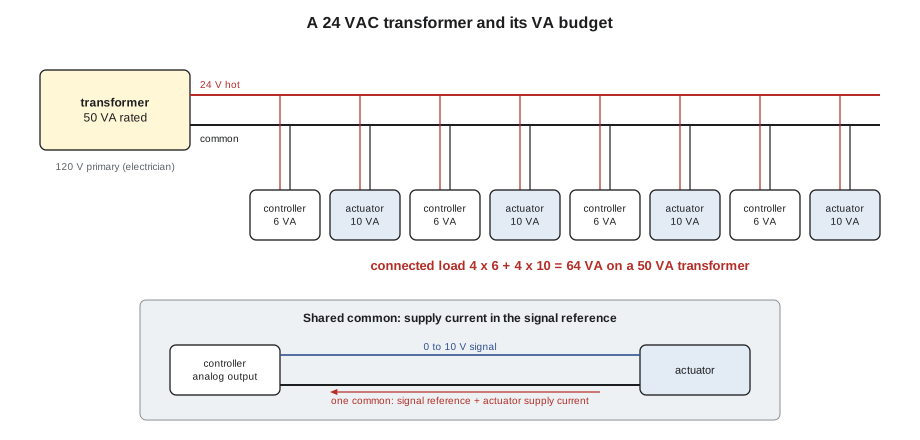
Tilden's west stair transformer fed four fan coil controllers at 6 VA each and four spring-return actuators at 10 VA each (the 2021 replacements; the originals were 2.5 VA). The transformer was rated 50 VA. What was the connected load, and how heavily loaded was it?
Show solution
- Controllers: 4 × 6 = 24 VA.
- Actuators: 4 × 10 = 40 VA.
- Connected load: 24 + 40 = 64 VA.
- 64 ÷ 50 = 1.28, so the transformer was at 128 in 100 of its rating whenever all four actuators drove at once.
- With the 100 VA transformer that Harcastle's electrician fitted early on September 29, the load is 64 ÷ 100 = 0.64 of the rating.
Answer: 64 VA on a 50 VA transformer, about 1.28 times its rating. With 100 VA fitted, the retest showed 24.6 V at the transformer and 23.4 V at the top controller, and the label now reads 64 VA connected, 100 VA rated.
The habit Prakash wants every technician to keep is simple: whenever you add or replace a device, add up the VA on that transformer and write the total on its label. Spring-return actuators, which have to wind a spring, and anything with a heater, such as some humidity sensors or a heated enclosure, can draw far more than the controllers. A transformer that was fine for years can become overloaded with one well-meant replacement.
Shared commons and polarity
A 24 VAC transformer secondary has two wires, often called hot and common, or 24 V and COM. In most controls installations, one side of the secondary is connected to ground so that all the devices on it share a reference. When several devices share one transformer, they must all be connected with the same polarity: every hot to hot, every common to common.
The reason is that many devices rectify the 24 VAC internally, and some use a half-wave circuit whose negative side is tied to the common terminal. If one device is wired with hot and common reversed, the common of that device is now at the hot potential, and if its common connects anywhere else, such as a shared analog signal common or the grounded side of the secondary, current flows where it should not. The result can be a blown fuse, a damaged output, or analog signals that read wrong. Tilden's 2023 file entry records exactly that: a swapped hot and common on one fan coil blew an actuator fuse.
Shared commons also cause trouble with analog signals. An analog output from a controller is measured from its signal common. If an actuator's power common and its signal common are tied together and run back on the same wire, the actuator's supply current flows in that wire and creates a small voltage drop. That drop adds to or subtracts from the signal the actuator sees. At Ninefield, the penthouse economizer actuators had shared one common with the analog outputs since 2019. When the actuators drove, the signal they saw shifted by a fraction of a volt, enough to move the dampers a few points away from their commands. Separate signal commons, run back to the controller's analog common, fixed it on November 9.
Voltage drop
Wire has resistance. Current through that resistance causes a voltage drop, so a device at the far end of a long run gets less voltage than the transformer supplies. On a 24 VAC circuit, a drop of a volt or two matters, because many controllers and actuators are rated for about 24 VAC plus or minus 20 in 100 (a typical tolerance; check the data sheet), so they may misbehave below about 19 to 20 V.
Worked problem
Voltage drop on a long actuator run
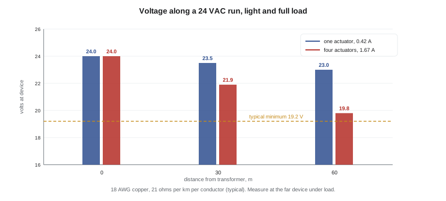
An actuator drawing 10 VA at 24 VAC is at the end of a 60 m (200 ft) run of 18 AWG copper. Using a typical resistance for 18 AWG of 21 Ω per km (6.4 Ω per 1,000 ft) per conductor, what is the voltage drop? What if four such actuators share the run?
Show solution
- Current for one actuator: 10 VA ÷ 24 V = 0.42 A.
- The current goes out and back, so the loop length is 2 × 60 = 120 m.
- Loop resistance: 120 m × 21 Ω per km = 2.5 Ω.
- Drop for one actuator: 0.42 A × 2.5 Ω = 1.05 V.
- Four actuators on the same run draw four times the current, about 1.67 A, so the drop is about four times larger: about 4.2 V.
Answer: About 1 V for one actuator, which is acceptable, but about 4 V for four sharing the run, which would leave the far devices near 20 V or below. Use heavier wire, shorter runs or separate runs from the transformer for heavy loads.
The cure for a voltage drop problem is to measure at the device, not at the transformer, under load. A transformer that reads 25 V with nothing driving can read 21 V when every actuator moves at once, and the devices at the end of the run see less again. Measuring both ends at the same moment, while the load is on, shows where the voltage is lost.
Loose, corroded and wrong connections
A loose terminal is one of the most common controls faults and one of the hardest to find, because it often comes and goes with temperature, vibration or someone opening the panel door. Its symptoms include intermittent communication on a network trunk, a sensor reading that jumps, an output that works only sometimes, and a controller that resets when an actuator moves.
- Tug test: with the circuit off or the input disabled, give each wire a gentle pull. A wire that slides out was never clamped.
- Look for insulation clamped under the screw instead of copper, or strands left outside the terminal.
- Look for corrosion on terminals in damp places: rooftop units, mechanical rooms with steam, cooling tower areas.
- Check ferrules on stranded wire where the terminal type needs them.
- Compare the terminations with the drawing. A jumper bar fault found on the bench test of Ninefield's RTU-1 panel in October would have been a field fault if the panel had not been tested before it left the shop.
Wrong connections are a separate family: a sensor landed on the wrong input, two wires swapped between adjacent terminals, a relay output wired to the wrong stage. At Ninefield's RTU-1 checkout on November 11, three faults turned up in 23 lines: the second cooling stage relay landed on the wrong unit terminal, the return and zone temperature sensors swapped, and the economizer actuator direction reversed. Point-to-point checkout exists to find exactly these faults, and when a system has never had a proper checkout, troubleshooting often turns into one.
Ground loops, induced voltage and noise
Analog signals and network communication are sensitive to unwanted voltages. Three sources are common.
A ground loop happens when a cable shield or a signal common is connected to ground at more than one point, and the two ground points are at slightly different potentials. A small current then flows in the shield or common, and the voltage it creates appears on the signal. The usual rule for shielded instrument cable in BAS work is to ground the shield at one end only, normally the controller end, and to tape back and insulate the shield at the device end. Network cable shields follow the manufacturer's rule for that network, which for MS/TP is usually one ground point per segment.
Induced voltage comes from nearby cables carrying changing currents. Variable frequency drive output cables are the worst offenders, because they carry fast switching pulses. A signal cable run alongside them for any distance picks up noise. At Ninefield on November 9, the chilled water differential pressure transmitter was jumping from sample to sample because its shield was grounded at both ends and its cable ran beside the drive output cables. Grounding the shield at one end and rerouting the cable fixed it, and the pump loop that had been hunting since October settled.
Electrical noise of other kinds comes from contactor coils, ignition transformers, welding, radios and poor power quality. Its fingerprint on a trend is random spikes or a value that jumps when a particular piece of equipment starts. The tests are to watch the signal while the suspect equipment cycles, to measure AC voltage on a DC signal line, and to check the shield and routing.
| Symptom | Likely wiring cause | Test |
|---|---|---|
| Controller resets when actuators move | Overloaded transformer or voltage drop | Measure voltage at the controller while commanding all actuators |
| Analog signal off by a fraction of a volt when outputs drive | Shared common carrying supply current | Measure signal between the actuator's signal terminals and at the controller; compare |
| Reading jumps or spikes when a drive or pump runs | Induced voltage, shield grounded at both ends | Measure AC on the signal line; check shield grounding and routing |
| Intermittent fault that changes when the panel is touched | Loose terminal | Tug test, visual inspection |
| Blown fuse or dead output after adding a device | Polarity reversed on a shared transformer | Check hot and common on every device on that transformer |
Measuring safely and accurately
Measuring is the least invasive way to test wiring, but only if it is done safely and correctly. Even in a Class 2 panel, the controls technician is often working beside line-voltage terminals: the transformer primary, a contactor's coil circuit, a drive's power terminals. Lesson 10 covers safe work on live systems in full. For measurement, a few rules matter most.
- Use a meter rated for the location. Meters carry a measurement category (CAT) rating and a voltage. For panels connected to building distribution, a CAT III rating at the panel's voltage or higher is the usual minimum; check your employer's rules.
- Check the meter on a known source before and after measuring, so that a dead reading means dead and not a broken meter or a blown meter fuse.
- Choose the right function. A 24 VAC supply is measured on AC volts; a 0 to 10 V signal on DC volts; a 4 to 20 mA loop with the meter in series, or with a clamp-type milliamp meter.
- Watch for ghost voltages. A high-impedance digital meter can read tens of volts on a disconnected wire that runs beside live ones, from capacitive coupling. A meter with a low-impedance setting helps tell a ghost from a real supply.
- Measure resistance only on dead circuits, with the device disconnected from the controller input, or the reading will include the controller's input circuit.
Record what you measure, with the time and the conditions: "21.3 V at transformer secondary with all four actuators driving, 7:40." A number without its conditions cannot be compared later.
Common mistakes
MistakeMeasuring transformer voltage with nothing running and calling the supply good.
InsteadMeasure under load, at the far device as well as at the transformer, when the symptom happens.
MistakeReplacing actuators with higher-VA models without checking the transformer.
InsteadAdd up the VA on that transformer after every change and update its label.
MistakeGrounding a signal cable shield at both ends for extra protection.
InsteadGround instrument shields at one end only, normally the controller end, to avoid a ground loop.
MistakeSharing one common for actuator power and analog signals to save a wire.
InsteadRun a separate signal common so supply current does not shift the signal.
Summary and key terms
- Most controls run on 24 VAC Class 2 power, limited to 100 VA per transformer; add up the VA of every device that can draw at once.
- Overloaded transformers sag under load and cause resets and intermittent faults that come and go with load.
- Devices on a shared transformer must all have the same polarity; reversed hot and common can blow fuses and damage outputs.
- Supply current in a shared common shifts analog signals; run separate signal commons.
- Voltage drop grows with current and run length; measure at the far device under load.
- Loose and wrong connections cause many intermittent faults; tug test, inspect and compare with the drawing.
- Ground shields at one end, keep signal cables away from drive output cables, and look for AC on DC signal lines.
- Measure with a meter rated for the location, checked on a known source, on the right function, and record the conditions.
- Class 2 circuit
- A power-limited low-voltage circuit, at 24 VAC limited to 100 VA, defined by the electrical code.
- VA budget
- The sum of the volt-ampere ratings of all devices on a transformer that can draw at once.
- Shared common
- One conductor used as the return for more than one device or signal.
- Voltage drop
- The loss of voltage along a wire caused by current flowing through its resistance.
- Ground loop
- Unwanted current in a shield or common grounded at two points at different potentials.
- Induced voltage
- Voltage picked up by a cable from nearby cables carrying changing currents.
- Ghost voltage
- A reading on a high-impedance meter caused by capacitive coupling, not a real supply.
Practice problems
Work each problem on paper first, then reveal the answer to check.
A controller resets every morning at 6:00 when the air handler starts. What wiring and power checks would you make?
Show answer
Add up the VA on its transformer, measure the voltage at the controller and at the transformer while the start sequence drives the actuators, and check for loose terminals and polarity on shared devices.
A valve actuator sits a few points away from its command whenever the other actuators on the same panel drive. What is the likely cause?
Show answer
A shared common carrying actuator supply current, shifting the analog signal reference. Run a separate signal common.
Why measure 24 VAC at the far device as well as at the transformer?
Show answer
Because voltage drop along the run can leave the far device below its minimum even when the transformer reads normal.
Lesson quiz · 5 questions
Score 60% or more to complete this lesson.
Create a free account to save your progress, take quizzes and earn a certificate.