
BAS-420 · Lesson 3 of 12 · 25 min
Field device faults
▶ Video coming soon A video version of this lesson is on the way.
"Half the calls in this binder," Prakash said, turning to the third tab, "end at a field device. A sensor reading wrong, an actuator that does not move the way the program thinks it does, a switch that tells a lie." The tab held a list in his handwriting of the field device faults Quillon had found at Harcastle and Ninefield since September, most of them with Callie there: a Type III thermistor on a Type II input, an actuator set for 0 to 10 V on a 2 to 10 V output, a filter switch with its tubes swapped, a building static tube cut by a roofer, a VAV box with the K-factor for a bigger box, a mixed air sensor with a kink in it, a current switch that could not see a broken belt. "Every one of these looked like something else first."
This lesson covers the common ways sensors, transmitters, switches and actuators fail or mislead, and how to test them in place. BAS-120 covered how these devices work and how to install them. Here the question is how to tell, quickly and with the least disruption, whether a field device is the cause of a symptom.
Three ways a field device can be wrong
A field device can fail in three broad ways, and each needs a different test.
- It can be broken: an open thermistor, a shorted transmitter, a burnt-out actuator motor, a stuck relay. Broken devices often give obvious readings: a temperature at the bottom or top of the range, a value that never moves, an actuator that never travels.
- It can be misconfigured: the wrong sensor type for the input, the wrong range or signal type, the wrong action or direction, the wrong K-factor. Misconfigured devices give readings that look plausible but are consistently wrong, often by a fixed amount or a fixed ratio.
- It can be in the wrong place or measuring the wrong thing: a sensor in stratified air, a zone sensor on a cold outside wall or above a printer, a pressure tube connected to the wrong port, a duct sensor in a dead corner. These readings are accurate for where the sensor is, but not for what the control loop needs.
Broken devices are found by testing the device. Misconfigured devices are found by comparing the device's data sheet with the controller's configuration. Misplaced devices are found by looking at where they are and comparing them with an independent reading taken where the measurement should be.
Temperature sensors
Most BAS temperature sensors are thermistors or resistance temperature detectors (RTDs). A thermistor's resistance falls as temperature rises; an RTD's rises. The controller turns the resistance into a temperature using a curve chosen in the input configuration. If the curve does not match the sensor, the reading is wrong by an amount that changes with temperature.
The basic test is to disconnect the sensor from the controller input, measure its resistance with a meter, measure the actual temperature beside it with a calibrated thermometer, and compare the resistance with the manufacturer's table at that temperature. An open circuit reads as infinite resistance; on a thermistor input, the controller then reports a very low temperature, often the bottom of its range. A short reads close to zero, and the controller reports a very high temperature. Many controllers also set the input's reliability to open loop or shorted loop.
Worked problem
A thermistor on the wrong curve
Tilden's outdoor air sensor was replaced in the summer with a 10K Type III thermistor, but the controller input stayed configured for 10K Type II. Both types read 10,000 Ω at 25 °C (77 °F). From manufacturer tables (typical values), a Type II reads about 32,650 Ω at 0 °C (32 °F) and a Type III about 29,490 Ω. What does the controller show when the real outdoor temperature is 0 °C (32 °F)?
Show solution
- At 0 °C (32 °F), the Type III sensor reads about 29,490 Ω.
- On the Type II curve, 29,490 Ω corresponds to about 2.0 °C (35.6 °F), because a Type II sensor would only fall to that resistance at a slightly warmer temperature.
- At −10 °C (14 °F) the error grows: the controller showed about −7.3 °C (18.8 °F).
- The two curves agree only near 25 °C (77 °F), which is why the sensor seemed fine on a summer day.
Answer: The controller reads about 2.0 °C (35.6 °F) at a true 0 °C (32 °F), and the error grows as it gets colder. A sensor curve mismatch gives an error that changes with temperature, unlike an offset, which is the same at every temperature.
Location faults are more common than broken sensors. In the lecture wing, AHU-2's discharge air probe sat only 0.6 m (2 ft) downstream of the heating coil, in air that had not yet mixed. It read the temperature of whichever layer of air happened to pass it, and that made the loop jumpy. At Marlow Lane, a zone sensor on VAV-2-09 read 0.7 K (1.3 °F) high because warm air from the wall cavity was blowing through the back box. On Ninefield's seventh floor, a humidity sensor in the return was seeing kitchenette air. None of these devices was broken. All of them were measuring something other than what the loop needed.
Averaging sensors fail in a special way. A long averaging element strung across a duct face averages the temperature along its whole length. If it is coiled in one corner, as Marlow Lane's mixed air sensor was at the pre-functional checklist, or kinked, as Tilden AHU-1's mixed air sensor was before Callie replaced it on November 2, it reads one part of the airstream. In a mixed air section, where cold outdoor air and warm return air may not mix well, that can be several degrees from the true average.
Pressure and flow sensors
Differential pressure transmitters and switches measure the difference between two ports. The most common faults are not in the transmitter at all but in the tubing: tubes swapped between high and low ports, a tube cracked, kinked, blocked with dust or water, or cut. Each gives a characteristic symptom.
- Swapped tubes on a transmitter: the reading goes the wrong way, often negative or pinned at zero, when the real pressure rises. On a filter switch with tubes swapped, the switch can never make, so it never alarms. Ninefield had a penthouse filter switch like that, also wired to the wrong contact.
- A cut or open reference tube: the transmitter reads against whatever pressure is at the cut end. At Ninefield, a roofer cut the building static outdoor reference tube in 2024, and the lobby was running at about +28 Pa (+0.11 in. w.c.) while the BAS showed it at its setpoint of +5 Pa (+0.02 in. w.c.).
- A blocked or waterlogged tube: the reading stops changing or changes slowly.
- A transmitter that needs zeroing: with both ports open to the same pressure, the reading should be zero. A small offset matters a lot on a low-range building static transmitter.
VAV box airflow depends on the flow pickup and on the configuration. The controller converts the velocity pressure from the pickup into airflow using a flow factor, often called the K-factor, for that box size and pickup. In BAS-120, VAV-2-07 at Tilden had the K-factor for a 250 mm (10 in) box on a 200 mm (8 in) box, so its displayed airflow was wrong at every flow. Three other boxes had cracked pickup tubes. A balancer's reading at the diffusers, compared with the box's displayed flow, is the usual test.
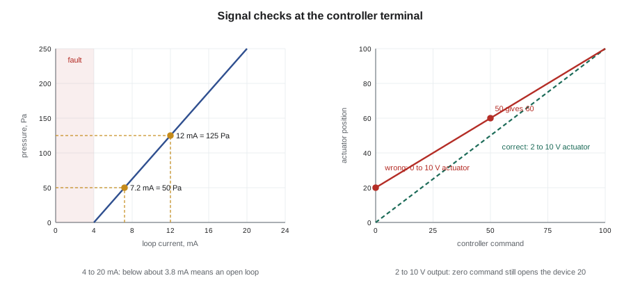
Current-signal transmitters, which send 4 to 20 mA, have a built-in test. A working loop never sends less than 4 mA, so a reading at or near 0 mA means the loop is open: a broken wire, a failed transmitter, or no loop power. Many controllers flag readings below about 3.8 mA or above about 20.5 mA as a fault (typical values; the exact limits depend on the controller).
Worked problem
Reading a 4 to 20 mA transmitter
A duct static pressure transmitter is ranged 0 to 250 Pa (0 to 1.0 in. w.c.) for 4 to 20 mA. With a meter in series, you read 12.0 mA, and the BAS shows 50 Pa (0.20 in. w.c.). What should the BAS show, and what does a 7.2 mA reading correspond to?
Show solution
- The signal span is 20 − 4 = 16 mA.
- At 12.0 mA: (12.0 − 4) ÷ 16 = 0.5 of span, which is 0.5 × 250 = 125 Pa.
- At 7.2 mA: (7.2 − 4) ÷ 16 = 0.2 of span, which is 50 Pa (0.20 in. w.c.).
- The BAS is showing the value for 7.2 mA while the meter reads 12.0 mA, so the transmitter is fine and the fault is between the meter and the value: input configuration, scaling or the wrong input.
Answer: The BAS should show 125 Pa (0.50 in. w.c.); 50 Pa (0.20 in. w.c.) corresponds to 7.2 mA. Since the measured current is right, check the input range and scaling in the controller.
Switches and status points
Status points answer yes or no questions: is the fan running, is the filter dirty, has the freezestat tripped? They fail by giving the wrong answer, and a wrong yes is more dangerous than a wrong no, because nobody looks for a fault that the BAS says is not there.
Current switches are the classic example. A current switch on a motor lead closes when the current is above its threshold. A fixed-trip switch with a low threshold closes for any running motor, including one spinning freely with broken belts. That is what happened on Tilden's EF-3, the chemistry lab exhaust fan, in early November. The motor drew about 7.4 A running normally and about 3.6 A with no belt, and the old switch closed for both. The replacement was an adjustable split-core switch set at 5.5 A, between the two, and an airflow switch was recommended for a lab exhaust where proof of airflow matters more than proof of current.
Other switch faults to know: a switch wired to the normally closed contact instead of the normally open one, which inverts its meaning; a differential pressure switch set so low that it makes on fan pressure alone; a freezestat or high static switch that was never wired into the fan circuit and only reports to the BAS. That last one is a safety fault, not just a status fault. AHU-2's freezestat, found in October, was wired only to a BAS input with a 15-minute alarm delay. Lesson 5 returns to it.
Actuators
An actuator is the device that moves a valve or damper. Its faults fall into the same three families: broken, misconfigured and mechanical.
| Fault | Symptom | Test |
|---|---|---|
| Signal range mismatch (0 to 10 V actuator on a 2 to 10 V output) | Device never fully closes; leaks heat or air at zero command | Measure the output voltage at 0 command; read the actuator setting |
| Reverse action set wrongly | Device moves opposite to the command | Command 0 and 100 and watch the position indicator |
| Floating actuator stroke time configured wrongly | Position the controller assumes drifts from the real position | Time a full stroke and compare with the configuration |
| Coupling or linkage slipping | Actuator moves, valve or damper does not, or not fully | Witness marks on stem and coupling; feel the pipe or look at the blade |
| Undersized actuator | Stalls part-way, especially against seals or high differential pressure | Compare actuator torque with the damper or valve requirement |
| No power or failed motor | No movement at all | Measure supply voltage at the actuator terminals |
Worked problem
An actuator set for the wrong signal range
In September, Tilden AHU-1's heating valve actuator was found set for a 0 to 10 V input, while the controller output was configured for 2 to 10 V (0 command = 2 V, 100 command = 10 V). Where did the valve sit at commands of 0, 50 and 100?
Show solution
- The controller output is 2 + 0.08 × command volts: 2.0 V at 0, 6.0 V at 50, 10.0 V at 100.
- An actuator set for 0 to 10 V opens 10 per volt: 2.0 V gives 20 open, 6.0 V gives 60 open, 10.0 V gives 100 open.
- So the valve was 20 open at a command of zero, and every position below 100 was higher than the program believed.
Answer: 20, 60 and 100 open. The heating valve could never close, which wastes heat and fights the cooling. Resetting the actuator's range switch to 2 to 10 V fixed it.
Floating, or tri-state, actuators have their own trap. The controller does not send a position; it drives the actuator open or closed for a time and estimates the position from the stroke time configured in the program. If the configured stroke time is shorter than the real one, as with a second-floor VAV reheat actuator at Tilden configured for 60 s when it really took 150 s, the controller believes the valve is much further open than it is. The fix is to time the real stroke and enter it, and to make sure the program drives the actuator fully closed from time to time to resynchronize.
Mechanical actuator faults are the most common and the easiest to miss from the screen. A coupling that slips on its stem, like room 108's reheat valve, lets the actuator travel while the valve stays put. A linkage on a damper can loosen so that the blades move only part of the way. A witness mark, a line drawn across the coupling and the stem with a paint pen, shows at a glance whether they have moved relative to each other. Quillon now marks every coupling it touches.
Testing a device in place
The least invasive test of a field device is a comparison: the BAS reading against your own measurement at the same place and time. For a temperature, that means a calibrated thermometer beside the sensor. For an actuator, it means watching the position indicator while someone commands the output. For a status point, it means looking at the equipment.
The next step is a signal check at the controller terminal: measure the voltage, current or resistance at the input or output, and compare it with what the controller shows. This is the split in the middle of the chain from lesson 1. If the terminal signal is right but the displayed value is wrong, the fault is in the configuration. If the terminal signal is wrong, the fault is in the device or the wiring.
Only after those tests should a device be disconnected or replaced. When a device is replaced, record the old and new part numbers, check that the replacement is the same type, range and curve, and update the points list. Tilden's outdoor sensor fault came from a replacement that was the right size and shape but the wrong curve.
Common mistakes
MistakeReplacing a sensor because its reading looks wrong, without measuring.
InsteadCompare with your own instrument first. The fault may be the input configuration, the wiring or the sensor's location.
MistakeAssuming an actuator is fine because its command and feedback agree.
InsteadFeedback comes from the actuator, not the valve. Check the coupling and linkage, and the effect downstream.
MistakeTrusting a current switch as proof of airflow.
InsteadA current switch proves current. Set its threshold between running and no-load current, or use an airflow switch where proof matters.
MistakeInstalling a replacement sensor that fits without checking its curve or range.
InsteadMatch the type, curve, range and signal to the controller's configuration, and update the points list.
Summary and key terms
- Field devices can be broken, misconfigured or in the wrong place; each needs a different test.
- Test a temperature sensor by comparing its resistance with the manufacturer's table at a measured temperature; a curve mismatch gives an error that grows away from the matching point.
- Most pressure sensing faults are in the tubing: swapped, cut, blocked or kinked.
- A 4 to 20 mA loop never runs below 4 mA when working; near 0 mA means an open loop.
- Status switches can give a wrong yes; set current switches between running and no-load current.
- Actuator faults include signal range and direction errors, wrong stroke times, slipping couplings and undersized actuators; witness marks make slipping visible.
- Measure at the controller terminal to split the chain between the device and the configuration.
- Thermistor
- A resistor whose resistance falls as temperature rises, used in most BAS temperature sensors.
- Curve (sensor type)
- The resistance-temperature table the controller uses to convert a sensor's resistance to temperature.
- K-factor
- The flow factor used to convert a VAV box's velocity pressure signal into airflow.
- Current switch
- A device on a motor lead that closes when the current is above a threshold.
- Floating actuator
- An actuator driven open or closed for a time, whose position the controller estimates from its stroke time.
- Witness mark
- A paint line across two parts that should not move relative to each other, so slipping can be seen.
Practice problems
Work each problem on paper first, then reveal the answer to check.
A zone sensor reads 1 K (2 °F) higher than your thermometer at every visit, winter and summer. Which kind of fault is most likely?
Show answer
A steady offset suggests a location or installation fault, such as air from the wall cavity through the back box, or an offset entered in the configuration, rather than a wrong curve, which would give an error that changes with temperature.
A 4 to 20 mA transmitter shows the bottom of its range and the meter reads 0.0 mA in the loop. What does that tell you?
Show answer
The loop is open or unpowered: a broken wire, a failed transmitter or missing loop power. A working transmitter never sends less than 4 mA.
Why is a slipping coupling hard to find from the front end?
Show answer
The actuator moves and reports the commanded position, so command and feedback agree; only the valve or damper fails to move. The clue is the effect downstream, such as discharge air temperature.
Lesson quiz · 5 questions
Score 60% or more to complete this lesson.
Create a free account to save your progress, take quizzes and earn a certificate.