
BAS-210 · Lesson 8 of 12 · 26 min
Configuring points and engineering units
▶ Video coming soon A video version of this lesson is on the way.
On Monday, October 26, after the morning review of AHU-1's start logic that BAS-130 described, Sophie Aubertin kept Callie in the office for the afternoon to build the database for the RTU-1 controller. The program logic was written and would be shared by all four Ninefield rooftop units. What remained was the part that made it RTU-1's: the points, their names, their units, their ranges, their alarm limits and the settings that decide how each one behaves on the network. "Logic is the brain," Sophie said. "Points are the senses and the vocabulary. If the points are wrong, the best program in the world is reading nonsense." This lesson covers what a point is, how it is named and configured, and how engineering units and scaling work.
What a point is
In building automation, a point is any single value the system knows about: a temperature, a status, a command, a setpoint, an alarm, a calculated value. Physical points, also called hardware points, are tied to a terminal on the controller: an input that reads a sensor or an output that drives a device. Virtual points, also called software points or values, exist only in the controller's memory: a setpoint, a mode, a calculated mixed air temperature, a flag set by the program. Both kinds look much the same from the front end, and both need careful setup.
In BACnet, each point is represented as an object of a standard type, with standard properties such as a name, a present value, units and status flags. The most common types are analog input, analog output and analog value; binary input, binary output and binary value; and multi-state input, output and value for points with several states, such as a mode with the states off, heat, cool and auto. BAS-310 covers BACnet objects in depth. For configuration, what matters is that every point has a set of properties to fill in, and each property affects how the point reads, displays, alarms or communicates.
| BACnet object type | Physical or virtual | RTU-1 example |
|---|---|---|
| Analog input | Physical input | Discharge air temperature |
| Analog output | Physical output | Economizer damper command |
| Analog value | Virtual | Occupied cooling setpoint |
| Binary input | Physical input | Supply fan status |
| Binary output | Physical output | Compressor stage 1 |
| Binary value | Virtual | Economizer enabled |
| Multi-state value | Virtual | Unit mode: off, heat, cool, fan only |
Naming points
A point's name is how operators, technicians and other systems find it. A good naming convention is consistent across the whole building, readable by a person and sortable by a computer. Most contractors and many owners have a standard, and a specification often sets one. A common pattern joins a site code, an equipment name and a point abbreviation, from general to specific. Quillon's convention used a two-letter site code, the equipment tag from the drawings and a short point code, separated by dots: TH.AHU1.MAT for Tilden Hall AHU-1 mixed air temperature, which BAS-120 described Callie wiring, and NF.RTU1.DAT for Ninefield RTU-1 discharge air temperature.
Names should match the equipment tags on the drawings and the labels in the panel, so that the same thing has the same name everywhere. Abbreviations should come from a fixed list, not be invented on the day: DAT always means discharge air temperature, not sometimes DA-T or SAT. Most systems also have a description property where a longer, plain-language description can go, such as RTU-1 discharge air temperature, after the heating section. Sophie was strict about this. A front end with one name for each thing makes trends, alarms and reports simple; a front end with three names for each thing makes them a puzzle.
| Code | Meaning | Code | Meaning |
|---|---|---|---|
| DAT | Discharge air temperature | SF-S | Supply fan status |
| RAT | Return air temperature | SF-C | Supply fan command |
| MAT | Mixed air temperature | CMP1 | Compressor stage 1 |
| ZNT | Zone temperature | HTG1 | Heating stage 1 |
| OAT | Outdoor air temperature | ECON-O | Economizer damper output |
| FLTR | Filter status | SMK | Smoke shutdown status |
Tags and data models
Names are made for people. Software that analyses data across many buildings, such as the analytics and energy tools covered later in the program, needs something more structured: a way to know that NF.RTU1.DAT is a discharge air temperature sensor on a rooftop unit that serves the podium, without parsing an abbreviation. Tagging and semantic data models do this by attaching standard labels or relationships to each point. Project Haystack uses tags such as discharge, air, temp and sensor. The Brick schema describes points and equipment as a linked model of what feeds what. ASHRAE has also developed a standard data model in this area. Some specifications now require tags or a model as part of the deliverables, and BAS-320 returns to them. For now, Callie added the Haystack tags Ilona's analytics provider asked for to each point in Sophie's template.
Engineering units
Each analog point carries engineering units: degrees Celsius or Fahrenheit, pascals or inches of water column, litres or cubic feet per minute, parts per million, a 0 to 100 command or position and so on. The units do two jobs. They tell people what the number means, and in BACnet they tell other devices too, through a standard units property. A point with the wrong units is as dangerous as a point with the wrong value: an operator who sees 500 with no units, or the wrong ones, may make the wrong decision. Units must also be consistent within a calculation. A program that subtracts a temperature in Fahrenheit from one in Celsius produces a number with no meaning at all.
Buildings in Canada are usually set up in SI units, but equipment data often comes in US customary units. Rooftop units are rated in tons of refrigeration, and many have nameplates in both systems. A technician needs to convert confidently and to know which units the controller is set to use.
| Quantity | SI | US customary | Conversion |
|---|---|---|---|
| Temperature | °C | °F | °F = °C × 1.8 + 32 |
| Temperature difference | K | °F | 1 K = 1.8 °F |
| Pressure (air) | Pa | in. w.c. | 1 in. w.c. = 249 Pa |
| Airflow | L/s | cfm | 1 L/s = 2.119 cfm |
| Water flow | L/s | gpm | 1 L/s = 15.85 gpm |
| Cooling capacity | kW | tons | 1 ton = 3.517 kW |
Worked problem
Converting units for a unit's data
RTU-1's nameplate gives a nominal capacity of 10 tons and a design airflow of 4,000 cfm. What are these in kW and L/s, and what is the airflow per ton?
Show solution
- Capacity: 10 × 3.517 = 35.2 kW.
- Airflow: 4,000 ÷ 2.119 = 1,888 L/s, about 1,890 L/s.
- Airflow per ton: 4,000 ÷ 10 = 400 cfm per ton, or 189 L/s per ton.
Answer: 35.2 kW and about 1,890 L/s, a typical 400 cfm per ton. Sophie set the controller's airflow display to L/s.
Ranges and scaling
For an analog input reading a voltage or current, the controller must be told how to turn the signal into engineering units. Most controllers use two-point linear scaling: the signal at the bottom of the range corresponds to one value and the signal at the top to another, with a straight line between. For a 0 to 10 volt CO2 transmitter with a range of 0 to 2,000 parts per million, 0 volts is 0 ppm and 10 volts is 2,000 ppm, so every volt is 200 ppm. Scaling must match the transmitter's own range setting exactly, which is why lesson 4's bench test injected known signals and checked the readings.
Worked problem
Linear scaling
A CO2 transmitter has a range of 0 to 2,000 ppm on a 0 to 10 volt output. The input reads 4.2 volts. What is the CO2 level? If the transmitter's range switch were actually set to 0 to 5,000 ppm, what would the true level be?
Show solution
- Scale: 2,000 ÷ 10 = 200 ppm per volt.
- Reading: 4.2 × 200 = 840 ppm.
- With a 0 to 5,000 ppm range: 4.2 × 500 = 2,100 ppm.
Answer: 840 ppm as configured. If the transmitter and controller ranges did not match, the true level would be 2,100 ppm while the front end showed 840, a dangerous mistake on a ventilation point.
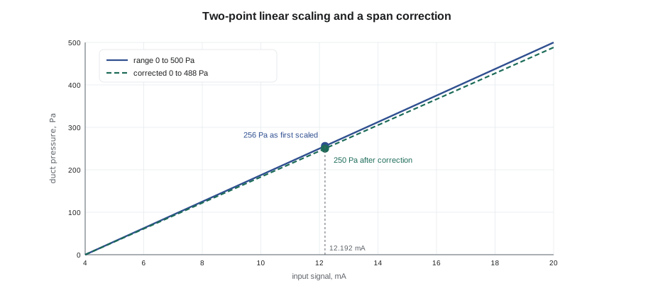
Scaling can also correct a sensor's error. If a check against a reference instrument shows that a transmitter reads correctly at zero but a little high at mid-scale, the top of the range in the controller can be adjusted so that the reading matches the reference. A small offset, a constant added to or subtracted from every reading, corrects a sensor that reads high or low by the same amount across its range, as BAS-120's calibration day described. Every such adjustment should be recorded, with the date and the reference used, because the next technician who replaces the sensor must remove it.
Worked problem
Correcting a span
A 0 to 500 Pa duct pressure transmitter reads 0 correctly. At a reference pressure of 250 Pa, the controller shows 256 Pa. What should the top of the controller's range be set to so that the reading matches?
Show solution
- Fraction of the signal at the reference: 256 ÷ 500 = 0.512.
- Correct span: 250 ÷ 0.512 = 488.3 Pa.
Answer: Set the top of the range to about 488 Pa, check again at a second pressure, and record the change. A transmitter that needs a large correction should be replaced.
Filtering, precision and change of value
Several smaller settings shape how a point behaves. An input filter, sometimes called damping, smooths a noisy reading by averaging it over a few seconds; too much filtering adds delay to a control loop, as BAS-130 found at Ninefield's pumps. Display precision sets how many decimal places are shown: a room temperature to one decimal is useful, a CO2 reading to one decimal is not. A change of value increment, in BACnet the COV increment, sets how much an analog value must change before the controller tells subscribed devices about it. A small increment gives fresh data but more network traffic; a large one keeps the network quiet but delays the news.
| Setting | Typical value | Effect if too small | Effect if too large |
|---|---|---|---|
| Input filter | A few seconds | Noisy reading and output | Lag in control loops |
| Display precision | One decimal for temperatures | Cluttered displays | Changes hidden from operators |
| COV increment | 0.2 to 0.5 K for temperatures | Heavy network traffic | Stale values at the front end |
| Alarm deadband | 0.5 to 1 K | Alarms that chatter on and off | Alarms that clear late |
Alarm limits and states
Points that matter get alarms. An analog point can have high and low limits, a deadband so that the alarm does not chatter when the value hovers near a limit, and a delay so that a brief excursion does not raise an alarm. A binary point can alarm on a particular state, such as filter dirty or fan failed, or on a mismatch between command and status, such as a fan commanded on whose status stays off. BAS-220 covers alarm logic and BAS-320 alarm management. At the configuration stage, the job is to set each limit to a value that means something to the operators and to record why.
For binary points, the configuration also says what the two states are called, which state is normal and, for inputs, which way round the contact works, as lesson 4 described. Sophie's template used plain state names: on and off for commands, running and stopped for status, normal and alarm for safeties. She had Callie check each binary input's polarity against the bench test results, because a fan status that reads running when the fan is stopped will hide a failure until someone complains.
Out of service, overrides and defaults
Every point also has properties that matter when things go wrong. In BACnet, an input or output can be put out of service, which disconnects its present value from the physical terminal so that a technician can write a test value. That is useful during checkout and dangerous if forgotten. Outputs and values can be commanded at different priorities, so that an operator's manual override wins over the program and a life-safety command wins over both; BAS-310 explains the priority array. Each output also has a relinquish default, the value it takes when no command is present at any priority, and the controller has a failsafe behaviour on power-up and loss of communication. These must match the sequence's intent: an economizer damper should go closed, not open, if the controller loses its program.
The RTU-1 database
By five o'clock, Callie and Sophie had configured every point in the RTU-1 controller from Sophie's template: 7 physical inputs, 6 physical outputs, 22 virtual points for setpoints, modes and calculated values, and the network outdoor air temperature from the supervisory controller. Each had a name from the convention, a description, units, a range or states, a COV increment, alarm limits where needed and Haystack tags. Sophie exported the point list to a spreadsheet for the job file and the panel's door pocket. "Now we can download it," she said. That was lesson 9's job.
Common mistakes
MistakeInventing abbreviations on the day.
InsteadUse a fixed abbreviation list and naming convention, matching the drawings and panel labels.
MistakeLeaving engineering units blank or wrong.
InsteadSet units on every analog point; they tell people and other devices what the number means.
MistakeScaling an input differently from the transmitter's range.
InsteadMatch the controller's range exactly to the transmitter's switch or jumper setting, and prove it.
MistakeMaking corrections without recording them.
InsteadRecord every offset or span change with the date and the reference used.
MistakeLeaving a point out of service after testing.
InsteadReturn every point to service and check the front end for out-of-service flags before leaving.
Summary and key terms
- A point is any single value the system knows: physical points are tied to terminals; virtual points live in memory.
- BACnet represents points as standard objects such as analog input, binary output and multi-state value.
- A naming convention joins site, equipment and point codes consistently, matching drawings and panel labels.
- Tags and data models such as Project Haystack and Brick let software understand points.
- Engineering units tell people and devices what a value means and must be consistent in calculations.
- Two-point linear scaling turns signals into values; offsets and span changes correct sensors and must be recorded.
- Filters, precision, COV increments, alarm limits, out-of-service flags and relinquish defaults all shape a point's behaviour.
- Point
- A single value known to the system, such as a temperature, status, command or setpoint.
- Physical point
- A point tied to a controller input or output terminal.
- Virtual point
- A point that exists only in controller memory, such as a setpoint or calculated value.
- Engineering units
- The units in which a point's value is expressed.
- Linear scaling
- Converting a signal to a value along a straight line between two set points.
- Offset
- A constant added to or subtracted from a reading to correct it.
- COV increment
- The change in an analog value that triggers a change-of-value notification.
- Out of service
- A BACnet flag that disconnects a point's value from its terminal for testing.
- Relinquish default
- The value an output takes when no command is present at any priority.
Practice problems
Work each problem on paper first, then reveal the answer to check.
Is an occupied cooling setpoint a physical or a virtual point?
Show answer
Virtual.
A 0 to 10 volt input is scaled 0 to 2,000 ppm. What does 6.5 volts read?
Show answer
6.5 × 200 = 1,300 ppm.
Convert 1,200 L/s to cfm.
Show answer
1,200 × 2.119 = 2,543 cfm.
Why must every offset be recorded?
Show answer
So that the next technician removes it when the sensor is replaced.
What should an economizer damper do if the controller loses its program?
Show answer
Go to its safe position, normally closed to minimum or fully closed as the sequence requires.
Lesson quiz · 5 questions
Score 60% or more to complete this lesson.
Create a free account to save your progress, take quizzes and earn a certificate.