
BAS-210 · Lesson 4 of 12 · 26 min
Universal inputs and outputs
▶ Video coming soon A video version of this lesson is on the way.
On Monday, October 5, the new controller for Ninefield RTU-1 was on the bench in the panel shop, and Callie's job for the morning was to set up its inputs and outputs before Sophie loaded the program. The controller had 10 universal inputs, 4 universal outputs and 6 relay outputs. Prakash gave her the point list Declan had drawn up and a box of test parts: a thermistor, a resistor decade box, a milliamp source, a 0 to 10 volt calibrator, a toggle switch and a meter. "Configure each one, then prove it reads or drives what it should," he said. "If it doesn't work on the bench, it won't work on the roof."
BAS-120 covered the signals that field devices produce and accept: resistance from thermistors and RTDs, 0 to 10 volts and 4 to 20 milliamps from transmitters, dry contacts from switches, and the analog and binary signals that drive actuators and relays. This lesson looks at the same signals from the controller's side: how universal inputs and outputs are configured to accept them, what the controller does inside, what the ratings in the data sheet mean and how to avoid the wiring mistakes that damage outputs.
What makes an input universal
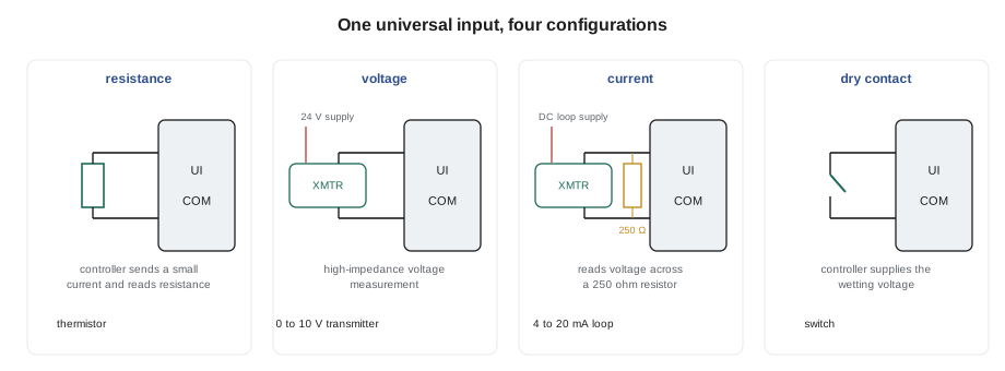
A universal input is a controller input that can be set up in software, and sometimes with a jumper or switch, to read several kinds of signal. A typical universal input can read a thermistor or RTD as a resistance, a voltage such as 0 to 10 volts, a current such as 4 to 20 milliamps, or a dry contact as a binary state. Some can also count pulses from a meter. Inside, the input has a measuring circuit that can be switched between modes: a small reference current for resistance, a high-impedance voltage measurement for voltage signals, a precision resistor for current signals, and a wetting voltage for contacts.
Universal inputs make controllers flexible: the same model can be used on many jobs, and a spare input can be used for whatever sensor is added later. The cost is that every input must be configured correctly, and a misconfigured input usually gives a believable but wrong reading rather than an obvious error. A 10K Type II thermistor read as a Type III, as BAS-120 described at Tilden, reads a few degrees off. A 0 to 10 volt transmitter read as 0 to 5 volts reads double. The point list should say exactly what each input is, and the bench test proves it.
Resistance inputs
For a thermistor or RTD, the input passes a small, known current through the sensor and measures the voltage across it, or uses a reference resistor and divider, to calculate the resistance. The controller then converts resistance to temperature using the curve for the selected sensor type: 10K Type II, 10K Type III, 1000 ohm platinum and so on, as BAS-120 explained. Because the measurement depends on the exact resistance, the wiring adds error on long runs, a small amount for 10K thermistors and more for low-resistance RTDs. A shorted sensor reads as a very high temperature on a thermistor input, because a thermistor's resistance falls as it warms, and an open one reads as very low. Many controllers flag readings outside the curve as a sensor fault.
Callie connected the decade box to input 1 with the input set for 10K Type II and dialled 10,000 ohms. The controller read 25.0 °C. She dialled 15,000 ohms and read about 16 °C, close to the Type II table in BAS-120. Then she set the input to Type III without changing the box and watched the reading move by several degrees, the same error Quillon had found at Tilden. She set it back and moved on.
Voltage inputs
For a voltage signal, the input measures the voltage between its terminal and common with a high input impedance, typically tens or hundreds of kilohms, so that it does not load the transmitter. The controller then scales the voltage to engineering units using the range set in the point configuration: for example, 0 volts is 0 parts per million and 10 volts is 2,000 parts per million of CO2. Many inputs can be set for 0 to 5 volts, 0 to 10 volts or 2 to 10 volts. The transmitter's own output range, set by its switches or jumpers, must match. A voltage input is wired with the signal to the input terminal and the transmitter's signal common to the controller's common, which, as lesson 3 explained, is usually also the 24 volt common.
Current inputs
For a 4 to 20 milliamp signal, the input passes the loop current through a precision resistor, usually 250 ohms, and measures the voltage across it. At 4 milliamps that is 1 volt; at 20 milliamps, 5 volts. Some controllers have the resistor built in and switched on by software; others need a jumper or an external resistor across the terminals. The controller then scales the current to engineering units. A reading below about 3.6 milliamps usually means a broken wire or a failed transmitter, and good programs alarm on it, which is one of the advantages of a live-zero signal. A two-wire, loop-powered transmitter also needs a DC loop supply in the circuit, from the controller's DC output terminals or a separate supply.
Worked problem
Scaling a 4 to 20 milliamp input
A duct static pressure transmitter has a range of 0 to 500 Pa and a 4 to 20 milliamp output. The controller's input reads 11.2 milliamps. What is the pressure, and what voltage appears across the 250 ohm resistor?
Show solution
- Fraction of span: (11.2 − 4) ÷ 16 = 0.45.
- Pressure: 0.45 × 500 = 225 Pa.
- Voltage: 0.0112 × 250 = 2.8 V.
Answer: 225 Pa, with 2.8 volts across the resistor. Measuring that voltage is a quick check that the loop and the scaling agree.
On the bench, Callie set input 6 for 4 to 20 milliamps, turned on the internal resistor in the configuration and connected the milliamp source. At 4.0 milliamps the controller read 0 pascals, at 12.0 it read half the range and at 20.0 the full range. Then she removed the source entirely and watched the input read about zero milliamps, below the live zero, which the program would later use as a transmitter fault alarm.
Binary inputs and dry contacts
A binary input set for a dry contact supplies its own small wetting voltage, often a few volts DC, and detects whether the contact across its terminals is open or closed. Dry means that the contact must have no voltage of its own: it is simply a switch, such as a current switch, a differential pressure switch or an auxiliary contact on a starter. Connecting a powered contact, such as one carrying 24 volts AC from another circuit, to a dry contact input can damage the input or give wrong readings. Where the status comes from a powered circuit, an interposing relay or an isolated input module separates the two.
Some status signals are wired normally open and some normally closed. A normally closed alarm contact, such as a freezestat's auxiliary contact or a smoke detector's trouble contact, opens on alarm and also opens if the wire is cut, which makes it fail-safe. The point configuration must state which way round each contact works, so that the controller reports normal and alarm correctly. Callie toggled the switch on input 9, the filter status, and set the point so that an open contact meant normal, matching the normally open filter switch on the unit.
| Input type | Configuration setting | What the controller does | Common mistake |
|---|---|---|---|
| Thermistor or RTD | Sensor type and curve | Measures resistance and converts with the curve | Wrong curve gives a believable but wrong reading |
| Voltage | Voltage range and engineering units | Measures voltage and scales it | Transmitter and input ranges do not match |
| Current | Current mode, resistor, units | Measures voltage across 250 ohms and scales it | Resistor not enabled, or no loop supply |
| Dry contact | Binary, normally open or closed | Supplies wetting voltage and senses the contact | A powered contact connected to the input |
| Pulse | Pulse counter and scale | Counts contact closures for a meter | Pulse too fast for the input, or wrong pulse value |
Analog outputs
An analog output produces a variable voltage, usually 0 to 10 volts or 2 to 10 volts, sometimes a 4 to 20 milliamp current. The controller's program produces a command, usually 0 to 100, and the output converts it to a signal using the configured range. An output can supply only a limited current, often around 10 to 20 milliamperes, so it is designed to drive the high-impedance signal input of an actuator or drive, not to power anything. Data sheets give a minimum load resistance, such as 1,000 ohms. Wiring the output to a low-resistance load, or shorting it to common, can damage it.
Worked problem
An analog output voltage
An economizer actuator takes a 2 to 10 volt signal. The program commands the damper to 45 in 100. What voltage should the output produce?
Show solution
- Span: 10 − 2 = 8 V.
- Voltage: 2 + 0.45 × 8 = 5.6 V.
Answer: 5.6 volts. Measuring the output against common and comparing it with the command is the first check when an actuator does not follow.
Analog outputs also need the right reference. The actuator's signal common must be connected to the controller's common, and as lesson 3 explained, both are usually the 24 volt common of the same transformer. Where the actuator has its own transformer, the two commons are still tied together so that the signal has a reference, which is only safe if both transformers' commons are on the same side and the makers allow it. When in doubt, power the actuator from the controller's transformer.
Binary outputs: relays and triacs
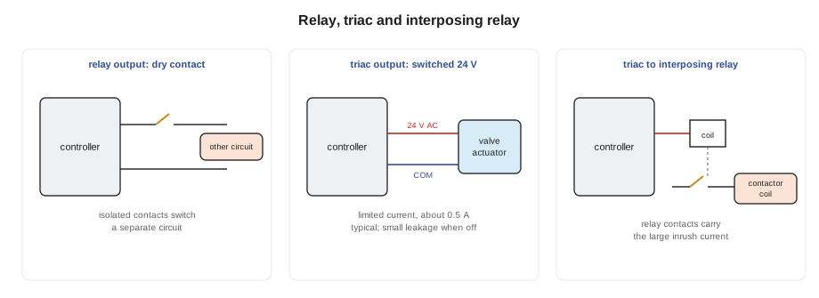
A binary output switches something on or off. Relay outputs have a small relay on the board whose contacts close a separate circuit. Because the contacts are isolated from the controller's electronics, a relay output can switch a circuit powered by another transformer, such as the 24 volt control circuit inside a rooftop unit, and data sheets give contact ratings such as 24 volts AC at 2 amperes. Some relay outputs are rated for 120 volts or more, but many controllers allow only Class 2 voltages on their outputs, and the ratings must be read carefully.
Triac outputs switch 24 volts AC electronically, with no moving parts. They are fast, silent and long-lived, but they can switch only AC, only within their current rating, often around 0.5 amperes, and usually only on the controller's own 24 volt supply. A triac also leaks a small current when off, which can keep a sensitive load, such as a small relay or an indicator, from releasing fully. Triacs suit valve actuators and small relays; they do not suit large contactor coils.
Worked problem
Checking a triac against a contactor coil
A contactor coil draws 7 VA when sealed and 40 VA for a moment when it first pulls in. It is to be driven by a triac output rated 0.5 A at 24 volts AC. Is it within the rating?
Show solution
- Sealed current: 7 ÷ 24 = 0.29 A.
- Inrush current: 40 ÷ 24 = 1.67 A.
- Inrush compared with the rating: 1.67 ÷ 0.5 = 3.3 times.
Answer: No. The sealed current is within the rating, but the inrush is more than three times it. That is what scorched the old controller in lesson 1. Use an interposing relay.
Interposing relays
An interposing relay is a separate relay, usually mounted on DIN rail in the panel, whose coil is driven by the controller's output and whose contacts switch the load. It is used when the load needs more current than the output can supply, when the load is at a different voltage such as 120 volts, or when the load's circuit must be kept separate from the controller's. The relay's coil must suit the output, for example a 24 volt AC coil within the triac's rating, and its contacts must suit the load. Where the contacts switch line voltage, the relay must be rated and installed for it, and the line-voltage side is electricians' work.
For RTU-1, Declan's design kept things simple. The rooftop unit had its own 24 volt control transformer and terminal strip, with terminals for fan, two cooling stages and two heating stages. The controller's six relay outputs would close dry contacts between the unit's R terminal and its G, Y1, Y2, W1 and W2 terminals, just as a thermostat does, keeping the unit's control circuit and Quillon's controller circuit separate. Callie tested each relay with the meter on continuity while Sophie's test page commanded it.
| Output type | Signal | Good for | Watch for |
|---|---|---|---|
| Analog voltage | 0 to 10 V or 2 to 10 V | Modulating actuators, drive speed | Minimum load resistance, shared common |
| Analog current | 4 to 20 mA | Long runs, some drives | Loop resistance limit |
| Relay | Dry contact | Switching another circuit, equipment enables | Contact voltage and current ratings |
| Triac | Switched 24 V AC | Valve actuators, small relays | Inrush current, leakage when off |
| Floating pair | Two triacs or relays | Floating actuators | Stroke time setting, both on at once |
Spares, labels and the point list
By noon Callie had configured and tested every input and output on the controller. She marked the three unused universal inputs, three unused universal outputs and one unused relay output as spares on the point list and added the configuration of each point: type, range, engineering units and normal state. That list, checked against the bench test, would go into the job file, and the same information would be printed on the panel's wiring diagram in lesson 5. "Write down what you set, not what you meant to set," Prakash said. "The controller will do what it was told."
Common mistakes
MistakeLeaving a universal input on its default type.
InsteadConfigure every input for the exact sensor or signal on the point list, and prove it on the bench.
MistakeConnecting a powered contact to a dry contact input.
InsteadDry contact inputs need a voltage-free switch; isolate powered signals with a relay.
MistakeForgetting the 250 ohm resistor or loop supply on a 4 to 20 milliamp input.
InsteadEnable or fit the resistor and provide the loop supply as the maker shows.
MistakeDriving a contactor coil from a triac because the sealed current fits.
InsteadCheck inrush current too, and use an interposing relay.
MistakeTreating an analog output as a power source.
InsteadAnalog outputs supply only a few milliamperes; respect the minimum load resistance.
Summary and key terms
- Universal inputs can be configured for resistance, voltage, current, dry contact and sometimes pulse signals.
- A misconfigured input usually gives a believable but wrong reading, so every input should be proved on the bench.
- Current inputs measure the voltage across a 250 ohm resistor; a reading below the live zero indicates a fault.
- Dry contact inputs supply their own wetting voltage and must not see outside voltage.
- Analog outputs produce 0 to 10 or 2 to 10 volt signals with limited current and need a shared common with the device.
- Relay outputs give isolated contacts; triac outputs switch 24 volts AC with limited current and some leakage.
- Interposing relays handle loads too large, at a different voltage, or in a separate circuit.
- Universal input
- A controller input that can be configured to read several kinds of signal.
- Wetting voltage
- The small voltage a controller applies to a dry contact to sense it.
- Dry contact
- A switch contact with no voltage of its own.
- Live zero
- A signal whose minimum value, such as 4 milliamperes, is above zero so that a broken circuit can be detected.
- Loop supply
- The DC supply that powers a two-wire current transmitter.
- Relay output
- A binary output with isolated relay contacts.
- Inrush current
- The brief high current a coil or motor draws when first energized.
- Interposing relay
- A separate relay driven by a controller output to switch a larger or separate load.
- Minimum load resistance
- The lowest resistance an analog output can drive without damage or error.
Practice problems
Work each problem on paper first, then reveal the answer to check.
A 4 to 20 milliamp CO2 transmitter covers 0 to 2,000 ppm. What does 14 milliamps mean?
Show answer
(14 − 4) ÷ 16 × 2,000 = 1,250 ppm.
What voltage across a 250 ohm resistor corresponds to 20 milliamps?
Show answer
0.020 × 250 = 5 volts.
A 0 to 10 volt output is commanded to 30 in 100. What voltage should it produce?
Show answer
3 volts.
A coil draws 24 VA at inrush. Can a 0.5 A triac drive it?
Show answer
24 ÷ 24 = 1 A, twice the rating, so no; use an interposing relay.
A thermistor input reads far too hot. What wiring fault is likely?
Show answer
A short across the sensor or its wires, since a thermistor's resistance falls as it warms.
Lesson quiz · 5 questions
Score 60% or more to complete this lesson.
Create a free account to save your progress, take quizzes and earn a certificate.