
BAS-210 · Lesson 12 of 12 · 26 min
Installing controls on a rooftop unit: a case study
▶ Video coming soon A video version of this lesson is on the way.
This lesson follows the whole RTU-1 job at Ninefield Tower, from the failure in August to the handover in November, as one story. Each earlier lesson took one part of it: the kinds of controller in lesson 2, power in lesson 3, inputs and outputs in lesson 4, the panel in lessons 5 and 6, the code and the electrician in lesson 7, the points in lesson 8, the download and backups in lesson 9, the trunk in lesson 10 and the checkout in lesson 11. Here they come together, with the decisions and the mistakes in the order they happened, and the lessons Quillon took into the December work on RTU-2 to RTU-4.
The failure and the quote
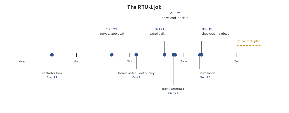
On Tuesday, August 18, the shops on Ninefield's podium reported no cooling. Quillon's service technician found RTU-1's 2004 unitary controller dead: no lights, no output, and a burned smell from its power supply. A replacement was no longer made, and the protocol converter that connected the old controllers to the building's BACnet network had no spare either. To keep the shops comfortable, he wired a temporary programmable thermostat to the unit's terminal strip, set to the shops' hours, and left a note on the front end that RTU-1 was off the network. The unit ran that way for almost three months.
Declan visited in early September and wrote the quote that lesson 2 described: a programmable BACnet controller for each of the four rooftop units on a new MS/TP trunk from the penthouse supervisory controller, one shared program written by Sophie, new sensors, a new spring-return economizer actuator on each unit, and the removal of the protocol converter once the last unit was done. On Monday, September 21, Ilona approved RTU-1 at once and the others for December, alongside the actuator replacements already booked.
Design decisions
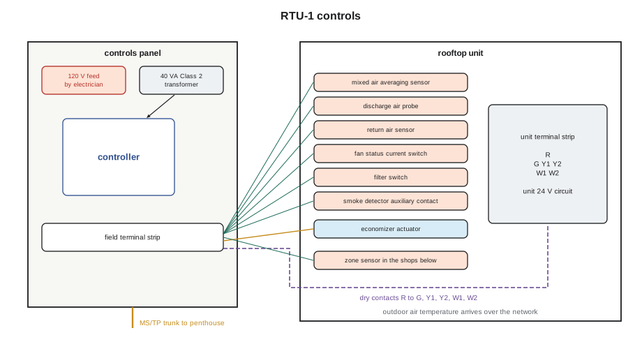
Several design decisions shaped everything that followed. The controller would sit in its own Type 4 enclosure on the unit's curb, not inside the unit's control compartment, because the compartment had no room and ran hot in summer. The controller's relay outputs would switch the unit's own 24 volt control circuit through dry contacts between the unit's R terminal and its G, Y1, Y2, W1 and W2 terminals, as a thermostat does, so that the unit's safeties, minimum run and off timers and gas ignition sequence stayed exactly as the manufacturer designed them. The controller and actuator would have their own 40 VA Class 2 transformer in the panel, fed by Kelso Electric's 120 volt circuit, and the controller's circuit and the unit's circuit would never share a common. The smoke detector would keep shutting the unit down through the unit's own wiring, with only an auxiliary contact to the controller.
| Decision | Reason |
|---|---|
| Separate Type 4 enclosure on the curb | Room, heat and weather; easy access for service |
| Relay outputs as dry contacts to the unit's terminals | Keeps the unit's own safeties and timers in charge |
| Own Class 2 transformer, separate from the unit's | No shared common between two control circuits |
| Smoke shutdown through the unit's own wiring | Life safety does not depend on the controller |
| New MS/TP trunk from the penthouse | Removes the protocol converter; one network for all four units |
| One program for all four units | Tested once, behaves the same everywhere |
Worked problem
Checking the point count
The RTU-1 controller has 10 universal inputs, 4 universal outputs and 6 relay outputs. The job uses 7 physical inputs, 1 analog output and 5 relay outputs. How many spares are there, and what fraction of the physical points is used?
Show solution
- Total points: 10 + 4 + 6 = 20.
- Used: 7 + 1 + 5 = 13.
- Spares: 20 − 13 = 7: 3 inputs, 3 universal outputs and 1 relay output.
- Fraction used: 13 ÷ 20 = 0.65, or 65 in 100.
Answer: Seven spare points, so the controller is about two thirds used, comfortably more than the 20 in 100 spare the design asked for.
Preparation in the shop
Most of the work happened before anyone climbed the roof. On October 5, Callie configured and tested every input and output on the bench, as lesson 4 described, and that afternoon walked the roof and the cable route with Declan and Tegan Farrow, as lesson 7 described. On October 21 she and Prakash built the panel, as lessons 5 and 6 described, sized the transformer at 40 VA for a 22.5 VA load and fitted a sun shield. On October 26 she and Sophie built the point database, and on October 27 Sophie downloaded the program and Callie took the first backup. By the time the panel left the shop, every point had been proved on the bench, and the only unknowns left were the field wiring and the unit itself.
Quillon's installation crew pulled the plenum-rated trunk cable through the communications riser and podium ceiling in the first week of November, landing it on a temporary terminal block on the roof. The roofing contractor made and sealed the sleeved penetration for the conduit, and Kelso Electric ran the 120 volt circuit and installed the disconnect on Monday, November 9, leaving the feed off and locked out at the panel in the electrical room.
Installation day
On Tuesday, November 10, Callie and Prakash arrived at seven with the panel in the van. The weather was cool and dry, which mattered: the unit would be off for most of the morning, and the shops opened at ten. They mounted the panel on its curb bracket on the north side of the unit, ran the short conduit from the roof penetration to the panel's bottom right entry and pulled the field cables into it. Tegan arrived at eight, landed her 120 volt feed on the panel's line-voltage terminals behind the barrier and confirmed the disconnect worked; the circuit stayed locked off until Quillon's pre-power checks were done.
Inside the unit, with the unit's own disconnect off and locked, they removed the temporary thermostat and its wiring, installed the discharge air probe in the supply duct downstream of the supply fan, where lesson 12 of BAS-130 had shown that the air is well mixed, and fitted the mixed air averaging sensor across the filter rack face, serpentined so that it covered the area evenly. They mounted the current switch on one supply fan motor lead in the unit's control compartment, set its trip point, and connected the filter switch tubes across the filter rack. The new spring-return economizer actuator went on the damper shaft with its fail position set to close the outdoor air damper. The zone sensor cable from the shops below came up through the unit's curb in its own gland. Then they landed everything at the panel's terminal strip and at the unit's terminal strip, marking every wire.
Worked problem
Checking the mixed air reading is plausible
At the minimum outdoor air setting of 20 in 100, with outdoor air at 2.0 °C and return air at 21.0 °C, what mixed air temperature should the new averaging sensor read?
Show solution
- Mixed air: 0.20 × 2.0 + 0.80 × 21.0 = 0.4 + 16.8 = 17.2 °C.
Answer: About 17.2 °C. The sensor read 17.5 °C, close enough given that the damper position is never exact. A reading of, say, 10 °C would have pointed to a sensor fault or a damper stuck far open.
The trunk and the network
At the panel, Callie landed the trunk on the network terminals with the shield on the panel's shield terminal and left the far end's shield floating, as lesson 10 described. RTU-1 was the only device yet on the new trunk, which ran from the router port on the penthouse supervisory controller to the roof; for now, it was both the last device and the end of the trunk, so its built-in terminator was switched on, and the router's was on at the other end. She wrote on the riser diagram that RTU-1's terminator would be switched off in December when RTU-2 to RTU-4 were added further along, with the terminator moving to the last of them. The MAC address, Max Master and baud rate matched the plan, and the device instance came from Quillon's numbering plan for the building.
Power-up and checkout
With the pre-power checks done, the 120 volt circuit was unlocked and the panel powered at 13:40. The controller came up, its heartbeat blinked, and within a minute RTU-1 appeared at the Ninefield front end with its new name and its points reading. The unit stayed off under the controller's control while the checkout began. Callie and Prakash worked through the inputs and the safeties that afternoon, and the outputs and equipment response the next morning, Wednesday, November 11, exactly as lesson 11 described. The three faults that lesson found were the most important results of the job: cooling stage 2 landed on a heating terminal, the return air and zone sensors swapped, and the economizer actuator's direction reversed. Each was found by a check that took a minute and would have taken a service call to find later.
By 11:00 on Wednesday the checkout sheet was complete, and Sophie, watching from the office, put the unit into its normal occupied schedule. Callie watched it for an hour on the roof: the supply fan proved, the economizer went to minimum position, the mixed air read sensibly and the shops' zone temperature drifted up toward setpoint with the first heat stage cycling. She took the site backup, NF_RTU1_2026-11-11_a, ran the override report until it was empty and returned the temporary thermostat to the service van's stock for the next emergency.
Hours and costs
Declan asked Callie to fill in the job's labour record, because the December quote for the other three units would be based on it. The comparison showed where the time had really gone.
| Task | Estimated hours | Actual hours |
|---|---|---|
| Bench configuration and test | 3 | 4 |
| Panel build and inspection | 6 | 7 |
| Point database and download | 3 | 3 |
| Trunk cable pull | 6 | 6 |
| Installation on the roof | 5 | 6 |
| Checkout and corrections | 3 | 5 |
| Total | 26 | 31 |
Worked problem
Comparing estimate and actual
The estimate was 26 hours and the actual was 31. By how much was the job over, as a fraction of the estimate, and what would the same overrun mean on three more units estimated at 20 hours each, given that the trunk is already pulled?
Show solution
- Overrun: 31 − 26 = 5 hours.
- Fraction: 5 ÷ 26 = 0.19, about 19 in 100 over.
- Three units at 20 hours: 60 hours.
- With the same overrun: 60 × 1.19 = 71.4, about 71 hours.
Answer: About 19 in 100 over, mostly in checkout and panel work. Declan kept the December estimate at 20 hours per unit but added the checkout corrections into each unit's allowance, rather than hoping for fewer mistakes.
What Quillon changed for December
Prakash, Declan and Callie held a short review on Thursday morning, November 12, before Callie went to Tilden Hall for the room 108 complaint that BAS-110 described. They agreed four changes for RTU-2 to RTU-4. The unit terminal strips would be photographed and their labels replaced before any wiring, because faded labels had caused the cooling and heating mix-up. Every sensor cable would be marked at the sensor end on the roof, not only at the panel, because the swapped sensors were indistinguishable at the terminal strip. The actuator direction switch setting for each damper linkage would be recorded on the drawing, so that the installer set it right the first time. And the bench test would include a full simulation of the unit's terminal strip with relays and indicator lamps, so that output wiring to the unit could be checked before going to the roof.
The December plan, written into the job file, was to install the three remaining panels in the first two weeks of December with the actuator replacements already booked, extend the trunk from RTU-1 to RTU-2, RTU-3 and RTU-4 in turn, move the trunk terminator to RTU-4, and remove the protocol converter once all four units were proven on the new network. Ilona would get one handover package for all four units: as-built drawings, point lists, checkout sheets, the final backups with firmware versions, and the sequence of operations.
What a technician should take from the job
Very little in the RTU-1 job was difficult. Each step was ordinary: configure the inputs, build the panel neatly, size the transformer, keep Class 2 apart from line voltage, name the points, back up the program, terminate the trunk, check every point. What made it a good job was that every step was done deliberately and written down, so that the three mistakes were caught on the roof instead of by the shops, and so that the next technician, in December or in ten years, could open the panel door and understand what was there. "That's the whole course," Prakash said, as they packed the van. "Know the box, respect the power, wire it like someone else has to fix it, and prove everything."
Common mistakes
MistakeWiring a controller's own transformer into the unit's control circuit.
InsteadSwitch the unit's circuit through dry contacts and keep the two commons separate.
MistakeLetting life safety depend on the new controller.
InsteadKeep smoke shutdown in the unit's own wiring, with only a status contact to the controller.
MistakeLeaving checkout to the end of the day.
InsteadPlan checkout time into the job; it is where the mistakes are found.
MistakeForgetting to plan the trunk's terminators for future devices.
InsteadRecord where the terminator will move when the trunk is extended.
MistakeEstimating the next job without learning from this one.
InsteadCompare estimated and actual hours and change the method, not just the numbers.
Summary and key terms
- The RTU-1 replacement used a programmable BACnet controller in its own Type 4 enclosure, switching the unit's own control circuit through dry contacts.
- The unit's safeties, timers and smoke shutdown stayed in the unit's own wiring.
- Bench configuration, a neatly built and certified panel, a correctly sized transformer and a complete point database came before the roof work.
- Installation kept Class 2 and line-voltage work separate, with the electrician's scope written down.
- The trunk was terminated at both ends, with a plan for moving the terminator in December.
- Checkout found three wiring and setup faults that would otherwise have become service calls.
- The job record and review changed the method for the next three units.
- Temporary thermostat
- A thermostat fitted to keep a unit running while its controls are replaced.
- Dry-contact interface
- Switching a unit's own control circuit with isolated relay contacts, as a thermostat does.
- Curb
- The raised frame on which a rooftop unit sits.
- Averaging sensor
- A long sensing element that reads the average temperature across a duct or coil face.
- Handover package
- The drawings, point lists, checkout sheets, backups and sequence given to the owner.
- Labour record
- The comparison of estimated and actual hours for each task of a job.
Practice problems
Work each problem on paper first, then reveal the answer to check.
Why did RTU-1's relay outputs switch the unit's R terminal to its G, Y and W terminals?
Show answer
To act as a thermostat does, leaving the unit's own safeties and timers in charge.
Why was RTU-1's terminator switched on, and when will it be switched off?
Show answer
It is the last device on the trunk for now; it will be switched off when RTU-2 to RTU-4 are added and the terminator moves to RTU-4.
Outdoor air 5.0 °C, return air 22.0 °C, 25 in 100 outdoor air. What mixed air temperature is expected?
Show answer
0.25 × 5.0 + 0.75 × 22.0 = 17.75 °C.
A job estimated at 40 hours took 46. What is the overrun?
Show answer
6 ÷ 40 = 0.15, 15 in 100.
Name two changes Quillon made for December after RTU-1.
Show answer
Any two of: photograph and relabel unit terminal strips first; mark sensor cables at the sensor end; record actuator direction settings; simulate the unit's terminal strip on the bench.
Lesson quiz · 5 questions
Score 60% or more to complete this lesson.
Create a free account to save your progress, take quizzes and earn a certificate.