
BAS-210 · Lesson 11 of 12 · 25 min
Checking out a new controller
▶ Video coming soon A video version of this lesson is on the way.
By the morning of Wednesday, November 11, the RTU-1 panel had been on its curb at Ninefield for a day. Lesson 12 tells the story of the installation on Tuesday. This lesson follows the checkout that Callie and Prakash did on Wednesday: the systematic proof, point by point, that every wire went where the drawing said, every input read the truth and every output did what it was told, before the unit was handed back to run on the new controller. "Checkout is where you find the mistakes," Prakash said as they climbed the roof ladder with the meter bag, a reference thermometer and a clipboard. "Everybody makes them. The difference between a good contractor and a bad one is whether the customer finds them first."
Checkout, start-up and commissioning
Three words describe the stages of bringing controls into service, and contractors and specifications use them in slightly different ways. Checkout, often called point-to-point checkout, proves that each physical point is wired, configured and working: the input reads the right sensor correctly and the output drives the right device. Start-up brings the equipment into operation under the new controls, often with the equipment manufacturer's representative for large equipment. Functional testing and commissioning prove that the whole sequence of operations works as designed, in every mode, and that the system meets the owner's requirements; the program's commissioning course covers these. Checkout comes first, because a sequence cannot be tested on points that are not proven.
| Stage | Proves | Done by |
|---|---|---|
| Pre-power checks | Wiring is safe to energize | Controls technician |
| Point-to-point checkout | Every physical point reads or drives correctly | Controls technician, often with a second person |
| Start-up | Equipment runs under the new controls | Controls technician, with the equipment maker where needed |
| Functional testing | The sequence works in every mode | Controls contractor and commissioning provider |
| Commissioning | The system meets the owner's requirements | Commissioning provider with all parties |
Before power is applied
The first checks are made with the panel de-energized. The technician compares the installed wiring with the drawing, terminal by terminal, and checks for anything that could damage the controller when power is applied: a short between 24 volts and common, line voltage connected to a Class 2 terminal, a shorted output or a powered contact on a dry contact input. A resistance check between the 24 volt supply terminals and between each output and common finds shorts. Where the panel has a line-voltage section, the technician confirms with the electrician that the feed is correctly connected and that the circuit is off and locked out until the checks are done.
On RTU-1, Callie checked the field terminal strip against the wiring diagram with a highlighter, as she had in the shop, and found the first problem before power was on: the wire from relay output 3, cooling stage 2, was landed on the unit's W2 terminal, heating stage 2, at the rooftop unit's own terminal strip. The two terminals were side by side and the labels on the unit's strip had faded. Commanding cooling stage 2 would have brought on the second stage of gas heat. She moved the wire to Y2, marked the change on the drawing and photographed the unit's strip for the job file.
Powering up
With the pre-power checks done, the panel is energized and the technician checks the basics: the transformer secondary voltage under load, the controller's status lights, the voltage at the controller's power terminals and at the furthest powered device, and the controller's own diagnostics. Callie measured 25.1 volts at the transformer and 24.9 at the controller with the actuator driving. The controller's heartbeat light blinked normally. Then she checked that the controller appeared at the front end with the right name and device instance and that its network status was online, which proved the trunk, the address and the baud rate from lesson 10 in one step.
Checking inputs
Each input is checked against a reference. A temperature sensor's reading at the front end is compared with a calibrated reference thermometer held next to it, as BAS-120's calibration day described, and the difference must be within the tolerance the specification sets, often about 0.5 K for air temperatures. A pressure reading is compared with a reference manometer. A status input is checked by making the real condition happen: the fan is started and the fan status must change, the filter switch is tested by blocking its high-pressure port, the smoke detector input by the detector's test function with the fire alarm contractor or building operator informed. Each result, the reference value and the reading go on the checkout sheet.
Worked problem
Checking a sensor against a reference
RTU-1's return air temperature reads 22.1 °C at the front end. The reference thermometer in the return duct beside the sensor reads 21.7 °C. The specification tolerance is 0.5 K. Does the sensor pass?
Show solution
- Difference: 22.1 − 21.7 = 0.4 K.
- 0.4 K is within the 0.5 K tolerance.
Answer: It passes. The reading and the reference go on the checkout sheet, so that a later drift can be seen.
On RTU-1, the return air and zone temperature readings looked plausible at first, but Callie noticed that when she warmed the wall sensor in the shop below with her hand, the return air reading rose. The two sensor cables had been landed on each other's inputs at the panel's terminal strip. Both were 10K Type II thermistors and both read about room temperature, so the swap was invisible until one was made to change. She swapped them back, warmed each sensor in turn to prove it, and marked the drawing. "That's why you make every input change," Prakash said. "A reading that looks right isn't proof."
Checking outputs
Each output is commanded from the front end or the controller's test page, and the result is observed at the device itself, not just at the controller. A binary output is turned on and off and the technician confirms that the right piece of equipment starts and stops. An analog output is commanded to several values, typically 0, 50 and 100, and the technician watches the actuator move to the matching positions and checks the voltage at the actuator's signal terminals. For actuators, the stroke direction, the end positions, the stroke time and, for spring-return actuators, the fail position when power is removed are all checked against the sequence.
Worked problem
Timing an actuator stroke
The economizer actuator's data sheet gives a running time of 90 s, within a tolerance of about 95 s maximum, and a spring-return time of about 20 s. Callie times a full stroke at 92 s open and 91 s closed, and the spring return at 18 s when power is removed. Do the results agree with the data sheet?
Show solution
- Driven stroke: 92 s and 91 s, both within the 95 s maximum.
- Spring return: 18 s, close to the 20 s typical figure.
Answer: Yes. The times go on the checkout sheet. A stroke much slower than rated can mean a binding linkage or damper; a spring return much slower can mean the damper is fighting the actuator.
When Callie commanded the economizer to 0, the outdoor air damper opened fully, and at 100 it closed. The actuator's direction switch had been left in the wrong position for this damper's linkage. Before changing anything, she checked that the spring return still closed the outdoor air damper when power was removed, because the fail position matters more than the direction switch. It did, which meant the actuator was mounted correctly and only the signal direction was reversed. She set the direction switch to match and recommanded 0, 50 and 100; the damper moved closed, half open and fully open, with the voltage at the actuator reading 2.0, 6.0 and 10.0 volts.
Proving the equipment responds
For each stage of heating and cooling, the technician commands it on and confirms that the equipment responds as it should: a compressor starts and the discharge air temperature falls; a heating stage lights and the discharge air rises. The size of the change is a useful check that the right stage came on and that the unit is working. Gas-fired rooftop units list an allowable temperature rise range across the heat exchanger on their nameplates, and the measured rise should fall within it.
Worked problem
Checking the heating temperature rise
With the supply fan running and both heat stages on, RTU-1's mixed air reads 14.0 °C and its discharge air settles at 33.5 °C. The nameplate gives an allowable rise of 17 to 39 K. Is the rise within range?
Show solution
- Rise: 33.5 − 14.0 = 19.5 K.
- 19.5 K is within the 17 to 39 K range.
Answer: Yes. The rise shows that both stages are firing with enough airflow. Gas appliance adjustments themselves are for a certified gas technician, not the controls technician.
Compressor stages were checked the same way, watching the discharge air fall with each stage, with the rooftop unit's own safeties and minimum run and off times left in place. Callie also checked that the controller's minimum off time prevented a compressor restart within the period the unit's maker required, by commanding stage 1 off and immediately on again and watching it wait.
Safeties and interlocks
Safety circuits are checked with particular care, because their failure is not visible in normal operation. On RTU-1, the smoke detector in the return air shut the unit down through the unit's own wiring, independently of the controller, and its auxiliary contact told the controller about the shutdown. With Ilona's building operator informing the fire alarm monitoring company, the detector was put into test, and Callie confirmed that the unit stopped, that the controller reported the smoke shutdown, and that the unit restarted only after the detector was reset. As BAS-130 described for AHU-1, the check was repeated with the controller powered down, to prove that the shutdown did not depend on the controller at all.
The checkout sheet
Every check is recorded on a checkout sheet. A typical sheet lists each point with its name, the terminal, the device, what was done, the expected result, the observed result, pass or fail, the initials of the person checking and the date. Failed points are corrected and rechecked, and the sheet shows both results. The completed sheet goes into the job file and the panel's door pocket, as lesson 6 described, and becomes part of the commissioning record. It is also the first thing a service technician should read on a later call.
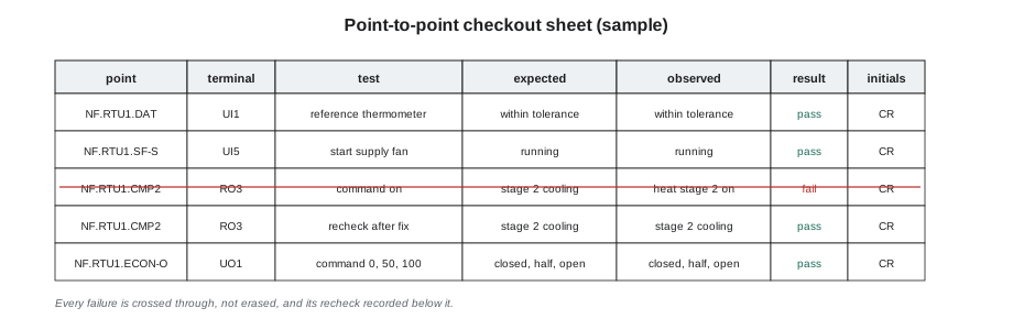
The RTU-1 sheet had 23 lines: the 13 physical points, the network outdoor air temperature, nine key virtual points such as setpoints and modes, and the communication check. Three lines had failed on first check: cooling stage 2 landed on a heating terminal, the return air and zone sensors swapped, and the economizer direction reversed. All three were corrected and passed on recheck. Prakash signed the sheet below Callie's initials, and she took the site backup, NF_RTU1_2026-11-11_a, as lesson 9 required.
Leaving the site
Before leaving, the technician returns every point to automatic: no outputs left in manual, no inputs left out of service, no test values left in place. A front-end report of points in override or out of service is the quickest check. The operator is told what was done and what to watch for. On RTU-1, Callie ran that report and found one point still in manual: the economizer, from her direction test. She released it, watched the damper go to its minimum position as the sequence required, and ran the report again until it was empty.
Working safely on the roof
Checkout on a rooftop unit means working beside rotating fans, hot heat exchangers, refrigerant lines under pressure and, inside the unit's control compartment, line voltage. The rules are the same as for any trade on a roof. The unit's disconnect is turned off and locked out before hands go into the unit, and the lockout is removed only when the person who applied it is clear. When equipment must run for a test, such as a fan status check or a heating temperature rise, the technician stays outside the unit's moving parts, keeps access panels in place or uses the unit's test ports, and tells everyone on the roof before starting it. Fall protection follows the building's rules and the roof's layout, as the trades safety courses describe.
Callie and Prakash agreed a simple routine for RTU-1: one person at the panel commanding outputs, one at the unit observing, a radio between them, and the unit's disconnect locked off whenever anyone reached inside. Before each start, the person at the panel said what was about to run and waited for the observer to answer clear. It slowed the checkout a little, and it was the only way Prakash would do it.
Common mistakes
MistakeApplying power before checking for shorts and wrong voltages.
InsteadDo the pre-power checks first; a single short can damage the controller.
MistakeAccepting a reading because it looks plausible.
InsteadMake every input change and compare it with a reference.
MistakeChecking outputs only at the controller.
InsteadObserve the result at the device: the right equipment, the right direction, the right positions.
MistakeFixing an actuator's direction without checking its fail position.
InsteadConfirm the spring-return position first; it matters more than the signal direction.
MistakeLeaving points in manual or out of service.
InsteadRun an override report and release everything before leaving.
Summary and key terms
- Checkout proves each physical point; start-up runs the equipment; functional testing and commissioning prove the sequence and requirements.
- Pre-power checks find shorts, line voltage on Class 2 terminals and wiring errors before energizing.
- Power-up checks cover voltages, status lights and the controller's presence on the network.
- Inputs are compared with references and made to change; outputs are observed at the device.
- Equipment response, such as a heating temperature rise within the nameplate range, proves the right stages operate.
- Safeties are tested with the controller both on and off.
- Every check is recorded on a checkout sheet, and every point is returned to automatic before leaving.
- Point-to-point checkout
- Proving that each physical point is wired, configured and working.
- Start-up
- Bringing equipment into operation under the new controls.
- Functional testing
- Proving that a sequence of operations works in every mode.
- Reference instrument
- A calibrated instrument used to check a sensor's reading.
- Stroke time
- The time an actuator takes to move from one end of its travel to the other.
- Fail position
- The position a spring-return actuator takes when power is removed.
- Temperature rise
- The increase in air temperature across a heating section.
- Checkout sheet
- The record of every point checked, its result and who checked it.
- Override report
- A front-end list of points in manual or out of service.
Practice problems
Work each problem on paper first, then reveal the answer to check.
A zone sensor reads 23.0 °C and the reference 22.4 °C. Tolerance is 0.5 K. Pass or fail?
Show answer
Difference 0.6 K, outside 0.5 K: fail; check the sensor and its location.
Why make every input change during checkout?
Show answer
A plausible reading can come from the wrong sensor, as the swapped return and zone sensors showed.
Mixed air 12.0 °C, discharge 31.0 °C, allowed rise 17 to 39 K. Within range?
Show answer
Rise 19.0 K: within range.
What should be checked before changing an actuator's direction switch?
Show answer
Its spring-return fail position.
What is the last check before leaving a site?
Show answer
An override report showing no points in manual or out of service.
Lesson quiz · 5 questions
Score 60% or more to complete this lesson.
Create a free account to save your progress, take quizzes and earn a certificate.