
BAS-210 · Lesson 3 of 12 · 26 min
Controller power, transformers and grounding
▶ Video coming soon A video version of this lesson is on the way.
On Monday, September 28, Nell Nakagawa called Quillon before eight o'clock. The fan coil controllers in Tilden Hall's west stair had dropped off the network again during the morning warm-up, as they had several times since the weather turned cool, and one of them had come back with its setpoint reset to the factory default. Prakash took Callie straight there. On the way he made a prediction: "Four controllers on one transformer, all dropping out at the same time on cold mornings. I'll bet you a coffee it's power, not programming." This lesson covers how controllers are powered, how transformers are sized and protected, and how the low-voltage circuits are grounded, using what they found in the west stair.
Why 24 volts AC
Building controllers and actuators in North America are almost all powered at 24 volts AC. The voltage is low enough that circuits limited to it, and to a modest amount of power, can be installed as Class 2 circuits, with lighter wiring methods than line-voltage circuits, as lesson 7 explains. It is also high enough to drive actuators, relays and valves over reasonable distances. A 24 volt control transformer steps line voltage, typically 120 volts, down to 24 volts. Many devices also accept 24 volts DC, and some transmitters need a DC supply, which a controller or a separate power supply provides.
A Class 2 transformer is one designed and listed so that the circuit it supplies is power-limited. In the Canadian Electrical Code, a Class 2 AC supply at around 24 volts is limited to roughly 100 volt-amperes, either inherently by the transformer's design or by a built-in overcurrent device. That is why control transformers for building automation are sold in sizes such as 40, 50, 75 and 100 VA and no larger. A load bigger than 100 VA needs more than one transformer, with each circuit kept separate as its own Class 2 circuit, or a Class 1 design.
Volt-amperes and sizing a transformer
Each controller, actuator, relay coil and powered sensor lists its power draw in volt-amperes on its data sheet. Actuators often list more than one figure: running, holding and, for spring-return types, the higher draw while the spring is being wound. To size a transformer, add up the volt-amperes of everything it feeds, using the highest figure each device can draw at the same time as the others, and add a margin, commonly 20 to 25 in 100, for voltage drop, aging and future additions. Then choose the next standard size up, staying within the Class 2 limit.
Worked problem
Sizing a transformer
A panel will power one controller at 12 VA, one spring-return economizer actuator at 7 VA running, a CO2 transmitter at 2 VA and an interposing relay coil at 1.5 VA. With a 25 in 100 margin, what transformer size is needed?
Show solution
- Total load: 12 + 7 + 2 + 1.5 = 22.5 VA.
- With margin: 22.5 × 1.25 = 28.1 VA.
- Next standard size: 40 VA.
Answer: A 40 VA Class 2 transformer, with room to spare. Lesson 12 uses this calculation for Ninefield RTU-1.
Transformers are rated at full load. At light load a 24 volt transformer often measures 26 to 28 volts, and at its full rating it should measure close to 24 volts. When a transformer is overloaded, its output voltage sags well below 24 volts and it runs hot. Most controllers have a minimum operating voltage, often about 20 volts, and below it they may reset, lose communication or behave erratically. Many actuators are rated for 24 volts plus or minus 20 in 100, which is 19.2 to 28.8 volts.
What the west stair showed
In the west stair, Callie found a 50 VA transformer in a small enclosure in the electrical closet, feeding four fan coil controllers and their four valve actuators. The controllers drew 6 VA each. The original valve actuators had drawn 2.5 VA each, but in 2021 they had been replaced with spring-return modulating actuators drawing 10 VA each while running. Nobody had resized the transformer. Prakash asked Callie to work out the load.
Worked problem
An overloaded transformer
Four controllers at 6 VA each and four actuators at 10 VA each share a 50 VA transformer. What is the total load, and what size should the replacement be with a 25 in 100 margin?
Show solution
- Controllers: 4 × 6 = 24 VA.
- Actuators: 4 × 10 = 40 VA.
- Total: 24 + 40 = 64 VA, which is 128 in 100 of the 50 VA rating.
- With margin: 64 × 1.25 = 80 VA.
- Next standard size: 100 VA, the largest Class 2 size.
Answer: The transformer was overloaded by more than a quarter whenever all four valves drove at once. A 100 VA Class 2 transformer covers the load with margin.
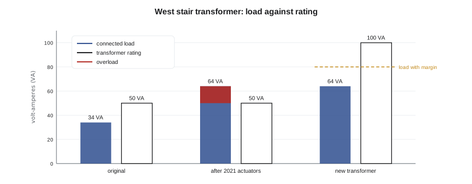
Callie put her meter on the transformer's secondary and asked Nell to put the four fan coils into morning warm-up from the front end, so that all four valves drove open together. The voltage at the transformer fell from 25.9 volts to 21.3 volts, and at the furthest controller, at the top of the stair, it fell to 19.8 volts. Within a minute, that controller's status light flickered and it dropped off the network. "Coffee's on you," Prakash said. The setpoint reset was explained too: that controller model kept operator-written values in working memory, and a brownout restart brought back the default stored in its program, the lesson 1 problem in real life.
Voltage drop on long runs
Even a correctly sized transformer delivers less than its terminal voltage at the far end of a long run, because the current flows through the resistance of both conductors, out and back. On 24 volt circuits, a drop of one or two volts is a large fraction of the supply. The drop is the current times the resistance of the round trip. For copper wire of about 0.82 mm², the resistance is about 20.9 ohms per kilometre of single conductor.
Worked problem
Voltage drop to a distant actuator
A 10 VA actuator is 60 m from its transformer on 0.82 mm² (18 AWG) copper. The transformer delivers 24 volts. What is the voltage at the actuator?
Show solution
- Current: 10 ÷ 24 = 0.417 A.
- Round trip: 2 × 60 = 120 m = 0.120 km.
- Resistance: 0.120 × 20.9 = 2.51 ohms.
- Drop: 0.417 × 2.51 = 1.05 V.
- Voltage at the actuator: 24 − 1.05 = 22.95 V.
Answer: About 22.9 volts, comfortably within a typical actuator's range. Several actuators on one run, or a sagging transformer, can add up quickly.
Where several devices share a long run, their currents add, and the voltage at the far end can fall below what the devices need. The cures are to keep transformers close to their loads, use heavier conductors for long power runs, or split the loads among more transformers. In the west stair, the drop in the riser added to the transformer's sag, which is why the top controller was always the first to drop out.
Protecting the circuit
A Class 2 transformer is either inherently limited, meaning that its windings cannot deliver dangerous power even into a short circuit, or protected by an internal fuse, circuit breaker or thermal cutout. Many controls panels also add a fuse on the 24 volt secondary to protect the wiring and devices and make a short easy to find. A 100 VA transformer at 24 volts delivers about 4.2 amperes at full load, so a secondary fuse of about 4 amperes is common. Smaller fuses are sometimes used on individual branches so that a fault on one actuator does not take down the controller.
The primary side of the transformer is a line-voltage circuit. It is fed from a branch circuit by a licensed electrician, and the transformer's primary protection follows the electrical code and the transformer's listing. A controls technician should not open line-voltage enclosures or rewire primary circuits unless qualified and permitted to do so under the rules where they work. At Tilden, Harcastle's own electrician replaced the transformer the next morning with a 100 VA unit, and Callie rewired the four secondaries with Prakash.
| Transformer | Full-load current at 24 V | Typical secondary fuse |
|---|---|---|
| 40 VA | 1.7 A | 2 A |
| 50 VA | 2.1 A | 2 to 2.5 A |
| 75 VA | 3.1 A | 3 A |
| 100 VA | 4.2 A | 4 A |
Hot, common and polarity
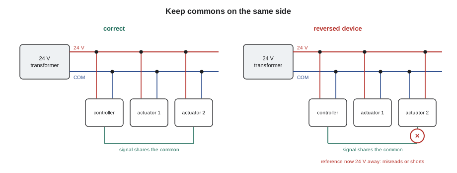
A 24 volt AC secondary has two wires. Although AC has no fixed positive and negative, controls manufacturers label one side 24 V, hot or R, and the other side common, COM or C, and the distinction matters. Inside many controllers and actuators, the 24 volt AC supply is rectified to DC by a single diode, a half-wave rectifier, with the common side shared between the power input and the signal circuits. That means the common terminal of the power supply is also the reference for the device's 0 to 10 volt signal. If several such devices share one transformer, every common must be on the same side of the transformer. If one device is wired with hot and common reversed, its signal reference is now at 24 volts relative to the others, and its signals read wrong or the circuit shorts through the internal parts.
A different problem appears when a device with a full-wave bridge rectifier shares a transformer with half-wave devices and one side of the transformer is grounded. In a full-wave bridge, neither supply terminal is the internal reference, so connecting the bridge's internal common to the shared grounded common can short part of the bridge and blow a fuse or damage the device. Manufacturers state whether a device is half-wave or full-wave and whether it may share a transformer with other devices. The rule that keeps technicians out of trouble is to read those instructions, keep commons consistent, and give a device its own isolated transformer whenever the maker requires it.
The Tilden service file had an entry from 2023 that Callie now understood: a replacement fan coil controller had been wired with hot and common swapped, and the valve actuator sharing its transformer had blown its internal fuse. The technician had corrected the wiring but not written down why. Callie added a note to the file.
Grounding
Two different ideas are both called ground in controls work, and confusing them causes faults. Earth ground, or the equipment grounding conductor, is the safety connection that bonds metal enclosures, panels and equipment to the electrical system's grounding, so that a fault trips the overcurrent device instead of leaving metal live. It is required by the electrical code and installed by the electrician. Signal common is the reference voltage that a controller's inputs and outputs measure against. Many manufacturers recommend that the 24 volt common be connected to earth ground at one point, usually at the transformer, so that the whole low-voltage system has a stable reference. Some require it to float. The controller's installation guide says which.
A ground loop happens when a signal circuit is connected to earth ground at two or more places that are not at exactly the same potential. A small current then flows through the signal common, and the voltage it creates adds to the signal. On a 0 to 10 volt input, a few tenths of a volt of ground loop error can mean a degree or more of temperature, or a damper that never quite closes. The cures are to bond the low-voltage common to earth at one point only, run each signal's common back with its signal on the same cable, ground cable shields at one end only as BAS-120 described, and use isolated inputs or 4 to 20 milliamp signals for long or noisy runs.
| Idea | Purpose | Who installs it | Rule of thumb |
|---|---|---|---|
| Earth ground | Safety: clears faults, bonds metal | Electrician, per the electrical code | Every metal enclosure and panel bonded |
| Signal common | Reference for inputs and outputs | Controls technician | Consistent side of the transformer, run with the signal |
| Common bonded to earth | Stable low-voltage reference | Controls technician, as the maker directs | At one point only, usually the transformer |
| Cable shield | Drains induced noise | Controls technician | Ground at one end only, usually the controller |
DC supplies for transmitters
Some sensors and transmitters need DC power: loop-powered 4 to 20 milliamp transmitters need a DC loop supply, often 24 volts DC, and some 0 to 10 volt transmitters accept only DC. Many controllers provide a small DC supply on terminals for this, with a current limit stated in the data sheet, such as 100 milliamperes in total. Where more is needed, a separate DIN-rail DC power supply is used. A technician should add up the transmitter currents just as for volt-amperes on the AC side, and check that a DC supply's negative is connected to the controller's common where the maker requires it, so the signals have the same reference.
The fix and the follow-up
Early on Tuesday morning, with the new 100 VA transformer in place and half an hour to spare before her tour of the central steam plant with Nell, Callie repeated the test. With all four valves driving open, the transformer held 24.6 volts and the furthest controller 23.4 volts, and no controller reset. She restored the operator setpoint on the controller that had lost it and, with Sophie's help, changed that model's configuration so that operator setpoints were stored permanently. Prakash asked her to write the transformer load on a label inside the enclosure: 64 VA connected, 100 VA rated, date and initials. "The next person to add an actuator will see the number," he said. "That's how this happened in the first place: nobody could see the load."
Common mistakes
MistakeReplacing actuators without checking the transformer.
InsteadAdd up the new load; spring-return and modulating actuators can draw far more than the originals.
MistakeWiring hot and common inconsistently on a shared transformer.
InsteadKeep every device's common on the same side, as the makers require.
MistakeGrounding the low-voltage common in several places.
InsteadBond it to earth at one point only, as the controller maker directs, to avoid ground loops.
MistakeMeasuring voltage only at the transformer.
InsteadMeasure at the furthest device under full load to see the real voltage.
MistakeExceeding 100 VA on one Class 2 circuit.
InsteadSplit larger loads among separate Class 2 transformers or use a Class 1 design.
Summary and key terms
- Building controls run on 24 volts AC from Class 2 transformers, limited to about 100 VA.
- Size a transformer by adding the volt-amperes of everything it feeds, adding a margin of about 20 to 25 in 100, and choosing the next standard size.
- An overloaded transformer sags; controllers below about 20 volts may reset or drop off the network.
- Voltage drop on long runs is the current times the round-trip resistance and can add to transformer sag.
- Half-wave devices share common between power and signal, so commons must be consistent; full-wave devices may need their own transformer.
- Earth ground is for safety; signal common is the reference; bond common to earth at one point only.
- DC transmitter supplies must be sized and referenced like the AC supply.
- Class 2 circuit
- A power-limited circuit supplied by a listed source, installed with lighter wiring methods.
- Volt-ampere
- The unit of apparent power used to rate transformers and device loads.
- Voltage drop
- The loss of voltage along conductors, equal to current times resistance.
- Half-wave rectifier
- A single-diode rectifier that shares one supply terminal with the device's internal common.
- Full-wave rectifier
- A bridge rectifier in which neither supply terminal is the internal common.
- Signal common
- The reference voltage against which inputs and outputs are measured.
- Earth ground
- The safety connection bonding equipment to the electrical system's grounding.
- Ground loop
- An unwanted current in a signal common caused by grounding at more than one point.
- Brownout
- A drop in supply voltage low enough to upset or reset electronic equipment.
Practice problems
Work each problem on paper first, then reveal the answer to check.
Three controllers at 8 VA and three actuators at 5 VA share a transformer. With a 25 in 100 margin, what size?
Show answer
Load 39 VA, × 1.25 = 48.8 VA, so a 50 VA transformer.
What is the full-load current of a 75 VA, 24 volt transformer?
Show answer
75 ÷ 24 = 3.1 A.
A 0.5 A load is 40 m away on 0.82 mm² copper. What is the drop?
Show answer
Round trip 80 m: 0.080 × 20.9 = 1.67 ohms; 0.5 × 1.67 = 0.84 V.
Why must commons be on the same side on a shared transformer?
Show answer
Half-wave devices use the common as the signal reference; a reversed device puts its reference at 24 volts and can short or misread.
Where should a cable shield be grounded?
Show answer
At one end only, usually at the controller.
Lesson quiz · 5 questions
Score 60% or more to complete this lesson.
Create a free account to save your progress, take quizzes and earn a certificate.