
BAS-130 · Lesson 11 of 12 · 23 min
Pneumatic and electric legacy controls
▶ Video coming soon A video version of this lesson is on the way.
On Thursday, October 8, the day after Callie had helped rewire AHU-2's freezestat, she went back to Tilden Hall with Prakash to look at the rest of the old air handler. AHU-2 serves the lecture wing and is due to be replaced in the summer of 2027. When the building's controls were converted to DDC in 2009, its large outdoor, return and relief dampers had kept their original pneumatic actuators, driven from the new controller through electric-to-pneumatic transducers; only the heating valve was given an electric actuator, in 2012. In the corner of the mechanical room, a small air compressor and dryer still ran to feed them. "You'll meet more pneumatics than you expect," Prakash said, opening the dryer's drain cover. "Half the buildings in this city still have some. And most of the people who knew them have retired."
Before electronic controls, buildings were controlled by compressed air. Pneumatic controls are robust, safe in explosive areas, cheap to actuate and very long-lived, and many are still in service, either whole or mixed with DDC. Older electric controls, using line-voltage thermostats, relays and potentiometer actuators, are also still found. This lesson explains how these legacy systems work, how they connect to modern controllers and what usually goes wrong with them, so that a technician can service them safely and plan their replacement sensibly.
How pneumatic control works
A pneumatic control system uses clean, dry compressed air as both its power and its signal. A compressor fills a receiver tank, and the air passes through a dryer and filters to a pressure-reducing valve that sets the main air pressure, typically about 140 kPa (20 psi) in buildings. Main air is piped to every controller. Each controller, such as a room thermostat or a receiver-controller, takes main air and produces a branch pressure, the control signal, which varies between about 20 and 100 kPa (3 and 15 psi) in proportion to what the controller wants. The branch line runs to the actuators, which move a valve or damper in proportion to the branch pressure.
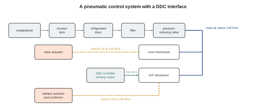
The standard signal range, about 20 to 100 kPa (3 to 15 psi), is a live-zero range, like the 4 to 20 mA signals of BAS-120. A branch pressure near zero means a broken line or a dead controller, not a command at the bottom of the range. Gauges on main and branch lines, often fitted at each controller, are the pneumatic technician's equivalent of a multimeter.
The air supply
Everything in a pneumatic system depends on the air being clean and dry. Moisture condenses in cold lines, freezes in lines that pass through cold spaces, and corrodes and swells the small orifices and diaphragms in controllers. Oil carried over from the compressor gums up the same parts. The air supply therefore has a refrigerated or desiccant dryer to remove moisture, filters to catch oil and dirt, and automatic drains on the receiver and dryer to dump the water that collects. Most pneumatic failures trace back to the air supply.
At AHU-2, the problem Prakash was looking for was there. The dryer's automatic drain had clogged, and when Callie cracked the drip leg on the main air line beside the air handler, a spoonful of water and a brown film came out. The damper actuators had been moving sluggishly on the trend for weeks. They cleaned the drain, blew down the drip legs, replaced the filter element and logged a request for Harcastle's mechanical contractor to service the compressor, which was due anyway.
| Air supply part | What it does | Common problem |
|---|---|---|
| Compressor and receiver | Produces and stores compressed air | Running too often because of leaks; oil carry-over in older units |
| Dryer | Removes moisture | Clogged drain or failed refrigeration, letting water into the lines |
| Filters | Remove oil, dirt and water droplets | Saturated elements that pass contaminants |
| Pressure-reducing valve | Sets main air pressure | Drifted setting; main pressure too high or too low |
| Drip legs and drains | Collect water at low points | Never drained |
Pneumatic thermostats and receiver-controllers
The simplest pneumatic controller is a room thermostat. A bimetal element bends with temperature and changes how much air escapes through a small nozzle, which changes the branch pressure. Direct-acting thermostats raise branch pressure as the room warms; reverse-acting ones lower it. Pneumatic thermostats are proportional-only controllers, which is why lesson 4 noted that rooms on them drift with load: there is no integral action to remove the offset. Their throttling range and setpoint are adjusted with small screws and need a calibrated gauge and patience.
Larger systems use transmitters and receiver-controllers. A pneumatic transmitter measures a temperature, humidity or pressure and sends a branch pressure across its range, for example 20 to 100 kPa (3 to 15 psi) for an outdoor temperature from −30 to 50 °C. A receiver-controller compares that signal with its setpoint and sends its own branch pressure to the actuators. Some receiver-controllers have proportional and integral action; many older ones are proportional only.
Worked problem
Reading a pneumatic transmitter
An outdoor air transmitter has a range of −30 to 50 °C over 20 to 100 kPa. What branch pressure should it send at 10 °C?
Show solution
- Span of temperature: 50 − (−30) = 80 K; span of pressure: 100 − 20 = 80 kPa.
- Fraction of range at 10 °C: (10 − (−30)) ÷ 80 = 0.5.
- Pressure: 20 + 0.5 × 80 = 60 kPa.
Answer: 60 kPa. A gauge on the transmitter's output reading well away from this, with the outdoor temperature known, points to a calibration or air problem.
Pneumatic actuators and spring ranges
A pneumatic actuator is a diaphragm or piston working against a spring. Air pressure on the diaphragm pushes the actuator stem out; the spring pushes it back. Each actuator has a spring range: the branch pressures at which it starts to move and at which it reaches full stroke. A common range is about 55 to 90 kPa (8 to 13 psi), and others such as 20 to 55 kPa (3 to 8 psi) are used. By choosing actuators with different spring ranges, a designer can sequence several devices from one branch line: the heating valve moves first, through the lower range, and the outdoor air damper moves later, through the higher range. That is the pneumatic version of the split-range sequencing in lesson 8.
With no air, the spring returns the actuator to its normal position. Normally open valves and normally closed dampers are chosen so that loss of air fails safe, the same reasoning as the spring-return actuators of BAS-120. An outdoor air damper is normally closed; a heating valve in a cold climate is often normally open.
Worked problem
An E/P transducer driving a pneumatic damper
AHU-2's controller sends a 0 to 10 V signal to an E/P transducer that produces 20 to 100 kPa. The outdoor air damper actuator has a spring range of 55 to 90 kPa. When the controller output is 6 V, what branch pressure results, and how far open should the damper be, assuming it follows its spring range exactly?
Show solution
- Branch pressure: 20 + 0.6 × 80 = 68 kPa.
- Damper position: (68 − 55) ÷ (90 − 55) = 13 ÷ 35 = 0.37, about 37 in 100 open.
Answer: 68 kPa and about 37 in 100 open. Below 55 kPa, or 4.4 V from the controller, the damper does not move at all.
Hysteresis and positive positioners
Real pneumatic actuators do not follow their spring ranges exactly. Friction in the damper linkage and the actuator itself means that the actuator needs a little more pressure to start moving one way and a little less to start moving back. The result is hysteresis: the position at a given branch pressure depends on which direction it came from. A heavy outdoor air damper can lag its command by several kilopascals, and the loop driving it sees a dead band it did not ask for, which can cause the limit-cycle hunting described in lesson 10.
The traditional cure is a positive positioner, or pilot positioner, mounted on the actuator. It senses the actual stem position through a feedback spring and supplies full main air pressure to the actuator until the position matches the branch signal. A positioner removes most hysteresis, lets an actuator work against higher loads, and can set its own start point and span, which makes sequencing more precise. AHU-2's outdoor air damper had a positioner; its return damper did not, and its trend showed the return damper lagging the outdoor damper by several seconds and a few hundredths of travel every time the mixed air loop changed direction.
Interfacing pneumatics with DDC
When a building is partly converted to DDC, two interface devices connect the two worlds. An electric-to-pneumatic transducer, or E/P, takes an analog output from the controller, such as 0 to 10 V or 4 to 20 mA, and produces a proportional branch pressure. A pneumatic-to-electric switch, or P/E switch, closes a contact when a pressure rises past its setting, for example to start a fan when a pneumatic thermostat calls. Pressure transducers convert a branch pressure into an analog signal so that a DDC controller can monitor a pneumatic controller's output.
E/P transducers need clean air as much as any pneumatic device, and they can drift. A check Callie learned that day was to command the E/P to known values, 0, 50 and 100 in 100 of output, and compare the branch gauge with the expected pressures. AHU-2's outdoor air damper E/P read 2 kPa high at mid-range, within the tolerance Prakash would accept; the return damper's E/P read low at the bottom of its range and could not fully close the damper, which they adjusted.
Retrofitting pneumatics
Pneumatic systems are eventually replaced, but the order matters. A common approach is to convert the controllers to DDC first and keep the pneumatic actuators, as Tilden did in 2009, because actuators are expensive to replace and often still sound. Later, actuators are replaced with electronic ones as they fail or as equipment is replaced. Wireless room sensors and pneumatic-to-digital retrofit thermostats can bring DDC-style control to terminal units without replacing the pneumatic tubing in the walls. Once the last pneumatic device is gone, the compressor and dryer can be removed, which also removes a source of noise, maintenance and energy use.
| Approach | Advantages | Drawbacks |
|---|---|---|
| Keep pneumatic actuators, add DDC controllers with E/P transducers | Lower cost; better control logic and trends | Air supply still needed; hysteresis remains |
| Replace actuators with electronic ones as equipment is replaced | Spreads cost; removes air dependence gradually | Mixed system for years |
| Full replacement with electronic actuators and DDC | Clean system; no compressor | Highest first cost |
| Retrofit wireless or pneumatic-to-digital thermostats at terminals | Little disruption to occupied spaces | Still needs main air for the terminal actuators |
For AHU-2, the decision was easy: the whole unit would be replaced in 2027, so Declan's proposal included new electronic actuators and removing the Tilden compressor, a plan rather than work already done. In the meantime, the job was to keep the pneumatic dampers working: clean, dry air; calibrated E/Ps; and a check of the positioners twice a year.
Electric and electronic legacy controls
Older electric controls are also still found. Line-voltage thermostats switch electric heaters and small fan coils directly. Relay logic panels, with timers and interlocking relays, run older air handlers and plant. A family of older modulating actuators uses a three-wire potentiometer signal, commonly a 135-ohm potentiometer in the controller driving a balancing relay in the actuator, which moves until a matching potentiometer on its shaft balances the bridge. And early electronic controls from the 1970s and 1980s used analog circuit boards before microprocessors took over.
When interfacing with these systems, the controls technician needs to know what kind of signal each device expects. A potentiometer actuator cannot be driven from a 0 to 10 V output without an interface module; a line-voltage thermostat cannot be monitored by a dry-contact input without an isolating relay. Electric legacy controls often run at line voltage, so the electrical safety rules from ELEC-110 apply, and line-voltage wiring belongs to a licensed electrician. Their drawings are also often missing or wrong. Prakash's advice was to trace every wire before trusting a diagram, and to label what you find for the next technician.
Common mistakes
MistakeIgnoring water in pneumatic drip legs.
InsteadDrain drip legs, check the dryer and its drain, and replace filters; most pneumatic faults start with the air supply.
MistakeTreating a near-zero branch pressure as a bottom-of-range command.
InsteadLike 4 mA, about 20 kPa is the live zero; near zero means a broken line or dead controller.
MistakeExpecting a pneumatic actuator to follow its spring range exactly.
InsteadAllow for hysteresis; use a positive positioner where precise or sequenced control is needed.
MistakeWiring a 0 to 10 V output straight to a potentiometer actuator.
InsteadUse the correct interface module for the actuator's signal type.
MistakeRemoving a compressor before every pneumatic device is gone.
InsteadConfirm that no actuator or controller still depends on main air.
Summary and key terms
- Pneumatic controls use compressed air: main air of about 140 kPa (20 psi) powers controllers, and branch pressure of about 20 to 100 kPa (3 to 15 psi) carries the signal.
- Clean, dry air is essential; dryers, filters and drains prevent most pneumatic failures.
- Pneumatic thermostats are proportional only; transmitters and receiver-controllers serve larger systems.
- Actuators work against springs with set spring ranges, which allow sequencing from one branch line and fail safe on loss of air.
- Hysteresis causes lag and limit cycles; positive positioners reduce it.
- E/P transducers and P/E switches connect pneumatics with DDC; check E/Ps at known outputs.
- Electric legacy controls include line-voltage thermostats, relay logic and potentiometer actuators, each needing the right interface.
- Main air
- The regulated compressed air supply that powers pneumatic controllers.
- Branch pressure
- The pneumatic control signal from a controller to its actuators.
- Receiver-controller
- A pneumatic controller that compares a transmitter's signal with a setpoint and sends a branch pressure.
- Spring range
- The branch pressures over which a pneumatic actuator moves from start to full stroke.
- Positive positioner
- A device on a pneumatic actuator that uses position feedback to make the actuator follow its signal accurately.
- E/P transducer
- A device that converts an electric control signal into a proportional branch pressure.
- P/E switch
- A switch that closes a contact when air pressure passes a setting.
- Hysteresis
- Lag in a device's response that depends on the direction of the change.
Practice problems
Work each problem on paper first, then reveal the answer to check.
An E/P produces 20 to 100 kPa from 0 to 10 V. What pressure does 2.5 V give?
Show answer
20 + 0.25 × 80 = 40 kPa.
A valve actuator has a 20 to 55 kPa spring range. How far open is it at 40 kPa?
Show answer
(40 − 20) ÷ 35 = 0.57, about 57 in 100 of stroke.
Why are pneumatic room thermostats prone to offset?
Show answer
They are proportional-only controllers with no integral action.
What usually causes sluggish pneumatic actuators?
Show answer
Contaminated air, often water or oil from a failed dryer, drain or filter.
What device converts a DDC analog output into a branch pressure?
Show answer
An electric-to-pneumatic (E/P) transducer.
Lesson quiz · 5 questions
Score 60% or more to complete this lesson.
Create a free account to save your progress, take quizzes and earn a certificate.