
BAS-130 · Lesson 10 of 12 · 29 min
Stability, hunting and loop problems
▶ Video coming soon A video version of this lesson is on the way.
On Thursday, October 15, Ilona Vescovi called Quillon about a noise. Tenants on Ninefield Tower's lower floors had noticed a faint rising and falling hum from the mechanical room every half minute or so. Callie and Prakash found the cause on the front end within ten minutes of arriving: the secondary chilled water pumps' speed was swinging steadily between about 44 and 58 Hz, with the pressure loop's output chasing the pumps' differential pressure up and down in a regular wave. The plant was holding its average pressure, but the pumps never settled. "That's hunting," Prakash said. "The question isn't whether it's a problem. It is. The question is why, and the answer's almost never just the tuning."
A stable loop settles after a disturbance. An unstable one swings back and forth, either indefinitely or with growing swings. In buildings, the common form is a steady, regular swing called hunting or cycling, and it is one of the most frequent loop problems a controls technician meets. Hunting wears out valves, actuators and drives, wastes energy, makes noise and upsets comfort. This lesson explains how to recognize it, how to tell its causes apart and how to fix each one, along with other common loop faults.
What hunting looks like
Hunting shows on a trend as a regular wave in the process variable and the output. Two numbers describe it: the amplitude, or how far it swings, and the period, the time for one full swing. A loop that hunts with a period of seconds is usually a fast loop such as pressure or flow; one that hunts with a period of many minutes is usually a temperature loop. The relationship between the process variable wave and the output wave, which one leads, and how sharp the turns are all give clues to the cause.
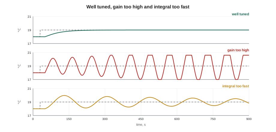
Not every swing is hunting caused by the loop itself. A loop can swing because something else is swinging and pushing it: another loop on the same system, a piece of equipment cycling on and off, a supply pressure that varies. Telling these apart is the first step in every hunting diagnosis.
The first test: put the loop in manual
The most useful single test for a hunting loop is to put it in manual, holding its output steady, and watch the process variable. If the swing stops, the loop was causing it: its tuning, its final element or its sensor. If the swing carries on with the output held still, the cause is outside the loop, and retuning will not help. At Ninefield, Prakash held the pump speed at 52 Hz for five minutes. The differential pressure became steady, apart from a slow drift as coil valves on the floors moved, so the loop was the source.
| With the loop in manual | Points to | Next step |
|---|---|---|
| The swing stops | The loop: tuning, final element, sensor or noise | Check mechanics and signal, then tuning |
| The swing carries on | Something outside the loop | Look for other loops, cycling equipment or supply variations |
| The swing changes period or size | Two or more loops interacting | Trend the related loops together |
Manual mode must be used carefully. A loop in manual cannot respond to load changes, so it should be watched and returned to automatic within minutes, and never left in manual at the end of a visit. Callie learned to put a note on the front end and in the work order whenever she put anything in manual, and to clear it when she returned it.
Tuning causes: too much gain or too fast integral
Once the loop itself is confirmed as the source, the next question is whether the settings are too aggressive. Too much proportional gain makes a loop overreact to every error, and the resulting swing is usually fairly fast, with a period of roughly two to four times the loop's dead time. Integral action that is too fast for the process gives a slower, rolling swing, often with a period several times longer, and the output tends to lag the process variable by a large fraction of a cycle. Lesson 6 described how to measure the dead time; comparing it with the period of the swing is a quick way to guess which setting is at fault.
Worked problem
Using the period to guess the cause
Ninefield's pump pressure loop was swinging with a period of about 32 seconds. A step test the previous spring, recorded in Quillon's file, had found a dead time of about 3 seconds and a time constant of about 8 seconds. The loop's integral time was 10 seconds. Which setting is more likely at fault?
Show solution
- A gain-driven swing would be expected at about 2 to 4 times the dead time: roughly 6 to 12 seconds.
- The observed period, 32 seconds, is much longer than that.
- An integral time of 10 seconds is close to the time constant, which would normally be reasonable, so a longer-period swing suggests something is adding delay or making the loop act on false information.
Answer: Neither setting alone explains the period. A swing much slower than the gain would cause, with sensible settings, points toward added delay or a noisy, filtered signal. That is where Prakash looked next.
Noise and filtering
Electrical noise on an input makes the process variable jump about. The loop reacts to every jump, and the output becomes jittery. Many controllers smooth inputs with a filter, but a heavy filter delays the signal, and delay is exactly what makes loops unstable. At Ninefield, the differential pressure input had been given a 15-second filter, probably by someone fighting the noise years earlier. The filter calmed the jitter but added enough delay to make the loop hunt slowly.
Worked problem
How much delay a filter adds
A first-order input filter with a time constant of 15 seconds is applied to a pressure signal. Roughly how long does the filtered reading take to show about 63 in 100 of a sudden real change? How does that compare with the process's own dead time of 3 seconds and time constant of 8 seconds?
Show solution
- A first-order filter with a 15-second time constant reaches about 63 in 100 of a step in 15 seconds.
- That is five times the process dead time and nearly twice its time constant.
Answer: The filter makes the loop see each change roughly 15 seconds late, slower than the process itself. The controller is effectively driving blind, and slow hunting results.
The cure for noise is to fix its source, not to bury it under filtering. BAS-120 lesson 9 covered shielding, grounding at one end, separation from power wiring and keeping signal commons apart. Prakash and Callie set an interim fix that day: they reduced the filter to 3 seconds and lengthened the integral time to 20 seconds, which stopped the hunting, though the pump speed still jittered slightly. The real fault, a cable shield grounded at both ends and run beside the drive output cables, was found and fixed on November 9, after which the filter could be reduced further and the loop returned to its original integral setting.
Final element problems
Many hunting loops are caused by the valve, damper or actuator rather than the settings. Three faults are common. Stiction, the static friction in a tight valve packing or a sticky damper, makes the final element stay still for small changes in command and then jump when the command has built up enough. The loop sees nothing happen, pushes harder, overshoots when the element finally moves, and repeats the cycle in a regular sawtooth pattern. Backlash, or slack in a linkage or coupling, does something similar: the actuator moves but the valve does not follow until the slack is taken up. Hysteresis in a pneumatic actuator, covered in lesson 11, has the same effect.
The signature of these faults is a limit cycle: a steady swing whose size depends on the amount of stiction or slack, not on the tuning. Retuning only changes the period. The test is to stroke the final element by hand or in manual in small steps and watch whether it follows each step. A month after the Ninefield visit, on November 12, Callie found a slipped coupling on a reheat valve actuator in Tilden room 108, a fault of exactly this kind but at its extreme, where the valve had stopped following the actuator altogether.
| Fault | What happens | Trend signature | Fix |
|---|---|---|---|
| Stiction | Element sticks, then jumps | Sawtooth output, square-ish process variable | Service or replace valve or damper |
| Backlash | Slack must be taken up before the element moves | Steady limit cycle; size depends on the slack | Tighten or replace the coupling or linkage |
| Undersized actuator | Actuator stalls under load | Output moves, process variable does not | Resize the actuator |
| Oversized valve | Most of the effect happens in a small part of travel | Hunting at low loads, fine at high | Correct the valve size or reduce gain at low output |
Oversized valves
An oversized valve passes the flow a coil needs at only a small opening, so a small movement of the valve makes a large change in heat transfer. In loop terms, the process gain is much higher than it should be, especially at low loads, and a loop tuned at high load hunts at low load. BAS-120 lesson 7 explained valve sizing and authority. From the controls side, an oversized valve is a nonlinear process: the right gain at one load is wrong at another.
Worked problem
Effect of an oversized valve on loop gain
A heating coil's valve was selected two sizes too large. At the coil's design flow the valve is only 25 in 100 open, instead of the 80 to 90 in 100 a well-sized valve would reach. Roughly how does that change the loop's gain at low and moderate loads compared with a correctly sized valve?
Show solution
- The full range of heat output is squeezed into about the first quarter of valve travel instead of most of it.
- Each unit of output therefore changes the heat delivered roughly 3 to 4 times as much as with a well-sized valve: 80 ÷ 25 = 3.2, or 90 ÷ 25 = 3.6.
Answer: The process gain is roughly three to four times higher, so settings that suit a well-sized valve make this loop hunt. The proper fix is the right valve; a short-term fix is a lower gain, accepting slower response.
Sensor location and dead time
Where a sensor sits affects both what it measures and how quickly it sees a change. A supply air sensor too close to a coil reads stratified air, hot or cold streaks that are not yet mixed, and jumps as the streaks move. One too far downstream sees changes late, adding transport delay: the time the air takes to travel from the coil to the sensor. Transport delay adds directly to the loop's dead time, and as lesson 6 showed, loops with large dead time must be tuned more gently.
Worked problem
Transport delay in a supply duct
A supply air sensor is mounted 15 m downstream of the coil, in a duct where the air moves at 2.5 m/s. How much transport delay does that add?
Show solution
- Delay = distance ÷ velocity = 15 ÷ 2.5 = 6 s.
Answer: About 6 seconds of extra dead time, small on its own but enough to matter on a loop whose own dead time is only 10 or 20 seconds. Sensors should be placed where the air is well mixed but no further away than necessary.
Averaging sensors, covered in BAS-120, solve the stratification problem on mixed air and coil leaving air without moving the sensor far downstream. Lesson 12 shows a case in which a single-point sensor's location contributed to a hunting discharge air loop.
Interacting and fighting loops
Loops that share a system can push each other around. A supply fan's static pressure loop and the VAV box flow loops it serves interact: when the boxes open, the static pressure falls, the fan speeds up, the pressure rises, and the boxes close again. A mixed air temperature loop on the dampers and a supply air loop on the coils interact through the same air stream. And heating and cooling loops can fight if their setpoints overlap, so that each undoes the other's work. Fighting loops show as two outputs moving in opposite directions together.
The fixes are structural. Make interacting loops respond at clearly different speeds, as lesson 7 described for cascades, with the faster inner loop tuned first. Separate heating and cooling setpoints with a deadband, or sequence them from one loop with dead zones, as lesson 8 showed. And trend related loops together, because a single loop's trend will never show the partner that is pushing it.
Other loop problems
Not every loop fault is a swing. A loop that sits at full output without reaching setpoint has a capacity or mechanical problem, as lesson 2 explained. A loop whose output is steady but whose process variable wanders has a final element that is not following its command. A loop that is slow to recover from every upset is too gently tuned or has a large dead time. A loop that drives to one end and stays there has its action reversed or its sensor failed. And a loop whose controller calculates too slowly, because its scan or update interval is long compared with the process, behaves as if it had extra dead time. Each has its own signature on a trend, and the table in lesson 2 is a good starting checklist.
Back at Ninefield, Callie wrote up the visit for Ilona: the pump loop's hunting had been stopped with an interim change to the input filter and integral time, and the likely cause was electrical noise on the differential pressure signal, to be traced on a later visit. The hum in the lower floors had gone by the time they left.
Common mistakes
MistakeRetuning a hunting loop before testing it in manual.
InsteadHold the output steady first; if the swing continues, the cause is outside the loop.
MistakeAdding heavy input filtering to hide noise.
InsteadFiltering adds delay and can cause slow hunting; fix the noise source.
MistakeRetuning to cure a limit cycle from stiction or backlash.
InsteadStroke the final element in small steps and repair the mechanical fault.
MistakeTuning an oversized valve's loop at high load only.
InsteadCheck the loop at low load, where an oversized valve's gain is highest.
MistakeMounting a supply air sensor far downstream to avoid stratification.
InsteadUse an averaging sensor closer to the coil, keeping transport delay small.
MistakeLeaving a loop in manual at the end of a visit.
InsteadNote every manual command and return it to automatic before leaving.
Summary and key terms
- Hunting is a regular swing in the process variable and output; its amplitude and period are the first clues.
- Putting the loop in manual shows whether the swing comes from the loop or from outside it.
- Too much gain gives a fairly fast swing, roughly two to four times the dead time; too fast integral gives a slower, rolling swing.
- Noise makes outputs jitter; heavy filtering adds delay and causes slow hunting; fix the noise source.
- Stiction, backlash and undersized actuators cause limit cycles that tuning cannot cure.
- Oversized valves raise the process gain at low loads and make loops hunt there.
- Sensor location sets stratification and transport delay; interacting and fighting loops need different speeds or deadbands.
- Hunting
- A steady, regular swing of a loop's process variable and output; also called cycling.
- Amplitude
- How far a swing goes either side of its average.
- Period
- The time for one complete swing.
- Limit cycle
- A steady swing caused by stiction, backlash or similar nonlinearity, whose size depends on the fault rather than the tuning.
- Stiction
- Static friction that makes a valve or damper stick and then jump.
- Backlash
- Slack in a linkage or coupling that must be taken up before the driven element moves.
- Transport delay
- The time a fluid takes to carry a change from where it happens to the sensor.
- Input filter
- Smoothing applied to an input signal, which reduces noise but adds delay.
Practice problems
Work each problem on paper first, then reveal the answer to check.
A loop hunts; in manual the swing stops. What does that tell you?
Show answer
The loop itself, its tuning, final element, sensor or signal, is causing the swing.
A loop with a 5-second dead time swings with a 15-second period. Which setting is a likely cause?
Show answer
Too much gain, since the period is about three times the dead time.
A sensor 10 m downstream in air moving at 4 m/s adds how much delay?
Show answer
10 ÷ 4 = 2.5 s.
What does a sawtooth output with a square-shaped process variable suggest?
Show answer
Stiction in the valve or damper.
Two loops' outputs move in opposite directions together. What is happening?
Show answer
They are fighting; separate them with a deadband or sequence them.
Lesson quiz · 5 questions
Score 60% or more to complete this lesson.
Create a free account to save your progress, take quizzes and earn a certificate.