
AUTO-420 · Lesson 8 of 12 · 20 min
Calibration basics: static, dynamic and the shop environment
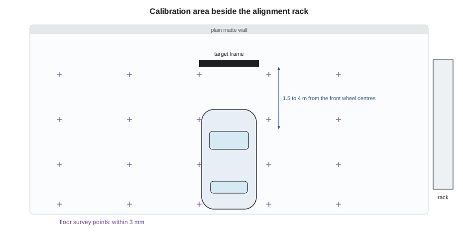
Building Ridgeline's calibration area took longer than Bev expected, and most of the time went into the floor. The space beside the alignment rack looked flat, but when Dale and Kiran surveyed it with a rotating laser level and a measuring staff at a grid of points, it fell 14 mm (0.55 in) from one corner to the other, with a low spot where an old floor drain had been filled. The target system's instructions, and most makers' procedures, required the floor under the vehicle and the target area to be level within a few millimetres over the whole working area. A contractor ground the high side and filled the low spot with a self-levelling compound, and the second survey passed.
This lesson covers what calibration is, the different kinds of calibration, and what a shop needs before it can calibrate anything: the information, the space, the lighting, the equipment and a correctly prepared vehicle. The next lesson carries out the calibrations themselves.
What a calibration does
Calibration tells a driver assistance module where its sensor is and which way it points relative to the vehicle's thrust line and the ground. The module needs that to turn what the sensor measures, angles and distances relative to the sensor, into positions relative to the vehicle. Some sensors are calibrated by aiming them mechanically, with an adjusting screw or a shim, so that they point exactly where the module expects. Most modern cameras, and many radars, are calibrated electronically: the sensor is left where it is, the module measures how it actually points, and it stores those angles as corrections. Many systems use both: a mechanical adjustment to bring the sensor within range, then an electronic calibration to fine-tune it.
Makers use different words for the same steps: calibration, aiming, alignment, initialization, learning, adaptation, teaching. The service information's wording matters because it says which routine to run and how. A technician follows the procedure for the exact vehicle, sensor and event, and records it.
Static, dynamic and self-calibration
There are three broad kinds. A static calibration is done in the shop with the vehicle stationary. Targets of a specified pattern, size and colour are placed at measured distances and heights in front of, behind or around the vehicle, aligned to the vehicle's centreline or thrust line. The scan tool starts the routine, the sensor views the target, and the module calculates and stores its angles. Forward cameras on many makes, surround view cameras, and many radars, using a metal reflector or a radar-specific target, are calibrated this way.
A dynamic calibration is done by driving the vehicle under specified conditions. The scan tool starts the routine, and the technician drives on roads with clear lane markings, at a set speed range, often with some traffic and roadside objects, for a set time or distance until the module reports that it has learned its angles. Many makers use dynamic calibration for forward cameras and some radars; some require both, a static calibration followed by a dynamic one. Dynamic calibrations depend on the weather, the traffic and the road: heavy rain, snow-covered lines or a road with too few markings can prevent one from finishing.
Self-calibration is the module's own ongoing correction of small changes while driving. It is how a camera adjusts for a slightly loaded rear end or a radar for a small bump. It cannot replace a required calibration after a repair, but its values, read on the scan tool, are useful clues.
| Kind | Where | What it needs | Typical uses |
|---|---|---|---|
| Static | In the shop | Level floor, clear space, correct targets at measured positions, controlled lighting | Forward cameras (many makes), surround view, radars with reflectors |
| Dynamic | On the road | Clear lane markings, set speed range, good weather, enough time | Forward cameras (many makes), some radars |
| Static then dynamic | Both | All of the above | Some makes' cameras and radars |
| Self-calibration | While driving | Normal driving | Small ongoing corrections only |
The space and the floor
A static calibration area needs room. Forward camera targets often stand 1.5 to 4 m (5 to 13 ft) in front of the vehicle's front axle or bumper, depending on the make, and some makes require more. Radar targets and reflectors often stand 1 to 5 m (3 to 16 ft) away. Surround view mats are laid around the whole vehicle, often 1 to 2 m (3 to 7 ft) beyond its outline. Beyond the targets, the area must be clear of objects that could confuse the sensors: shelves, parked vehicles, tool carts and reflective surfaces for radar, and patterned walls, signs and bright lights for cameras. Many shops paint the wall behind the target area a plain, matte neutral colour.
The floor is the hardest part. The vehicle, the target stand and the mats must all sit on the same plane, because a slope between them tilts the sensor's view of the target and puts a pitch or roll error into the calibration. Most target system makers and vehicle makers specify a maximum slope over the working area, typically a few millimetres over several metres, and Ridgeline adopted a tolerance of ±3 mm (±0.12 in) across the calibration area. Some target systems compensate for small floor slopes by measuring them, and some alignment-rack-based setups calibrate with the vehicle on a levelled rack.
# Floor survey: heights at grid points relative to the first point, checked against the tolerance
heights = [  # rows front to back, columns left to right, mm
    [0, 1, 2, 2, 1],
    [1, 1, 2, 3, 2],
    [0, 1, 1, 2, 2],
    [-1, 0, 1, 1, 1],
]
for row in heights:
    for k in range(len(row)):
        row[k] *= 1
tol = 3
flat = [h for row in heights for h in row]
spread = max(flat) - min(flat)
print(f"highest {max(flat)} mm, lowest {min(flat)} mm, spread {spread} mm")
print("area within tolerance" if spread <= 2 * tol else "area out of tolerance: correct the floor or use slope compensation")
for r, row in enumerate(heights):
    for c, h in enumerate(row):
        if abs(h) > tol:
print(f"point row {r + 1}, column {c + 1}: {h} mm beyond {tol}")highest 3 mm, lowest -1 mm, spread 4 mm area within tolerance
Lighting and background
Cameras calibrate by finding the target's pattern in the image, so lighting matters. Most procedures call for even, diffuse lighting on the target without glare, reflections or shadows across it, and no bright light sources such as windows, open doors or work lights in the camera's view behind the target. Strong sunlight through an open bay door in the late afternoon can cause a calibration to fail or, worse, to pass with a poor result. Ridgeline closed the window behind the calibration area and fitted diffuse overhead lights, and Kiran keeps the bay door closed during camera calibrations.
Radar calibrations have their own environment needs: no metal objects in the radar's field near the reflector, no other vehicle's radar operating close by, and a clear path between the radar and the target, which for some makes means removing a front licence plate bracket or emblem cover during the procedure.
Preparing the vehicle
A sensor's view of the target depends on the vehicle sitting exactly as it sits on the road, so the maker's procedure lists the vehicle's condition. The usual list is: correct tire sizes, matching on each axle, at the placard pressures; a fuel tank full or at a stated level, because fuel weight changes ride height; the cargo area empty and no passengers; the vehicle at its specified ride height, including air suspension set to its normal level; the wheel alignment within specification, and on many makes checked or corrected first, because the thrust line is the reference; the steering wheel straight and the steering angle sensor centred; and the windshield, bumper cover and sensor area clean and undamaged. Doors are closed, and the engine or the vehicle's ready mode is on for the routine with a battery support unit connected, because calibrations can take many minutes and a voltage drop can abort them.
# Pre-calibration checklist for a vehicle (values recorded at the start of the job)
checks = {
    "tires match on each axle": True,
    "tire pressures at placard": True,
    "fuel at least 3/4 or full": False,
    "cargo area empty": True,
    "ride height in specification": True,
    "alignment checked, thrust angle in specification": True,
    "steering angle sensor at zero": True,
    "windshield and sensor areas clean, undamaged": True,
    "battery support unit connected": True,
    "bay door closed, lighting even": True,
}
open_items = [k for k, ok in checks.items() if not ok]
for k, ok in checks.items():
    print(f"[{'x' if ok else ' '}] {k}")
print("ready to calibrate" if not open_items else f"not ready: {', '.join(open_items)}")[x] tires match on each axle [x] tire pressures at placard [ ] fuel at least 3/4 or full [x] cargo area empty [x] ride height in specification [x] alignment checked, thrust angle in specification [x] steering angle sensor at zero [x] windshield and sensor areas clean, undamaged [x] battery support unit connected [x] bay door closed, lighting even not ready: fuel at least 3/4 or full
The thrust line deserves its own note. Driver assistance modules treat the direction the vehicle travels, set by the rear wheels, as straight ahead. Targets are aligned to that line, usually with a laser or a line marked from the rear wheel centres, and the forward camera and radar are calibrated to it. If the thrust angle is out of specification when the sensors are calibrated, they are calibrated to a line the vehicle does not follow, and the lane and forward features will be off. That is why so many makers require an alignment check before a calibration, and why the alignment rack and the calibration area at Ridgeline sit side by side.
Information and equipment
Every calibration begins with the maker's procedure for that vehicle: the event that triggers it, the sensors involved, the kind of calibration, the targets and their positions, the vehicle preparation and the acceptance criteria. Ridgeline's sources are the makers' service information subscriptions, an aftermarket calibration database cross-checked against the maker, and the I-CAR calibration requirements search, which lists the events that require calibration by year, make and model.
The equipment list follows from the procedures: a scan tool able to run each maker's routines, with current software and the security access some makes require; a target frame with a laser system to centre and square it to the vehicle; the target boards for each make, which differ in pattern and size; radar reflectors and alignment tools; surround view mats; a battery support unit; a laser level and staff for floor checks; and a tape, plumb bob and calibration documentation forms. Targets must be kept clean, flat and undamaged, because a scratched or warped board can cause a poor calibration.
The documentation matters as much as the work. Ridgeline's calibration record for each job lists the vehicle, the trigger event, the procedure and its source, the floor and lighting check, the vehicle preparation readings, the pre-calibration scan, the calibration performed and its result as reported by the module, the post-calibration scan and the road test. A printed or saved scan report goes with the repair order.
Worked problem
Does the floor slope matter?
A camera target stands 3.0 m (9.8 ft) in front of the camera. If the floor under the target is 6 mm (0.24 in) lower than under the vehicle, what pitch error does that put into the calibration?
Show solution
- Angle = arctan(height difference ÷ distance).
- 0.006 ÷ 3.0 = 0.002 (0.24 ÷ 118 = 0.0020).
- arctan(0.002) = 0.11 degrees.
Answer: About 0.11 degrees of pitch error. Small, but at 150 m (490 ft) it moves the camera's estimate of where an object sits on the road by a noticeable amount, and it adds to every other small error.
Keeping the area ready
A calibration area only stays accurate if it is treated as one. Ridgeline's rules, posted on the wall, are short: nothing stored in the target zone or against the plain wall, no vehicles parked in the area when it is not in use, floor marks kept clean and visible, targets stored flat in their cases away from heat and sunlight, and the floor re-surveyed every six months and after any floor repair. The laser units are checked against a reference line monthly, and the scan tool's software and the makers' subscriptions are renewed before they expire. Dale added the area to the shop's weekly safety walk, because a cart or a tire stack left in the target zone is easy to miss until a calibration fails.
Common mistakes
MistakeCalibrating on a floor that has not been surveyed.
InsteadCheck the floor against the tolerance and record it.
MistakeCalibrating with sunlight or work lights in the camera's view.
InsteadClose doors, control lighting and keep the background plain.
MistakeSkipping the alignment check before a forward sensor calibration.
InsteadThe sensors are calibrated to the thrust line; it must be correct first.
MistakeIgnoring fuel level, cargo and tire pressures.
InsteadThey change ride height and the sensor's angle.
MistakeRunning a long routine without battery support.
InsteadA voltage drop can abort the calibration.
Summary and key terms
- Calibration tells a module where its sensor is and which way it points, relative to the thrust line and the ground.
- Static calibrations use targets in the shop; dynamic calibrations use driving; some makes require both.
- Self-calibration corrects small changes but does not replace a required calibration.
- A static calibration area needs clear space, a plain background, controlled lighting and a level floor.
- The vehicle must be prepared: tires, fuel, cargo, ride height, alignment, steering centre, clean sensors, battery support.
- The thrust line is the reference for forward sensors, so alignment comes first.
- Every calibration follows the maker's procedure and is recorded with scans and a road test.
- Static calibration
- A calibration done with the vehicle stationary and targets at measured positions.
- Dynamic calibration
- A calibration done by driving under specified road and speed conditions.
- Thrust line
- The direction the rear wheels point the vehicle; the reference for straight ahead.
- Target
- A board, reflector or mat of specified pattern and size used for a static calibration.
- Floor survey
- Measuring floor heights at grid points to check the calibration area is level.
- Battery support unit
- A power supply that holds system voltage steady during long routines.
Practice problems
Work each problem on paper first, then reveal the answer to check.
Why did Ridgeline have the floor ground and filled?
Show answer
It fell 14 mm (0.55 in) across the area, beyond the level tolerance.
What can stop a dynamic calibration from finishing?
Show answer
Bad weather, covered or missing lane markings, or the wrong speed or traffic conditions.
Why must the alignment be correct before calibrating a forward camera?
Show answer
The camera is calibrated to the thrust line.
Name four items on the vehicle preparation list.
Show answer
Tire sizes and pressures, fuel level, empty cargo area, ride height, alignment, steering centre, clean sensors, battery support.
Lesson quiz · 5 questions
Score 60% or more to complete this lesson.
Create a free account to save your progress, take quizzes and earn a certificate.