
ARCH-230 · Lesson 9 of 12 · 22 min
Load paths in buildings
Szymańska starts the ninth class at the top of the school's main stair with a bag of marbles. She asks Ingrid to imagine that each marble is a small piece of the snow on the roof, and to describe its journey to the ground. Ingrid starts confidently: the snow presses on the roof membrane, the membrane on the insulation, the insulation on the roof deck. Then she hesitates. Does the deck rest on joists or on beams? Which way do the beams span? Do the columns above the third floor land on the columns below, or on a beam? Twenty minutes later, with help from the drawings and from Callum, the marble reaches the footings. 'A building is a set of paths,' Szymańska says. 'Every load must find one, all the way to the ground. Your job is to make the paths short, direct and continuous.'
The gravity load path
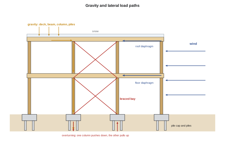
A load path is the route a load takes from where it is applied to the ground. In a typical building the gravity load path runs from the roof or floor surface into the deck or slab, from the deck into the joists or secondary beams, from those into the main beams or girders, from the girders into the columns or bearing walls, from the columns down through every storey to the foundations, and from the foundations into the soil. At each step the load is gathered from a wider area and concentrated into fewer, larger members. Each transfer happens at a connection, and each connection must be designed for the force it passes on.
The order of spanning members is called the framing hierarchy. In the hub's wing, the CLT floor panels span about 3.5 m between glulam beams, the beams span 7.2 m between columns, and the columns carry the loads to pile caps. In the hall, the roof deck spans between purlins, the purlins between trusses, and the trusses between columns in the east and west walls. Drawing the hierarchy on a framing plan, with arrows showing which way each member spans, is the first step in any structural layout, and it is the drawing the engineer will ask for first.
Continuity and alignment
The best load paths are direct: columns stack one above another from roof to foundation, bearing walls align from floor to floor, and loads travel straight down. Each time a column or wall stops above an opening and its load must be picked up by a beam, called a transfer beam or transfer girder, the load takes a detour, and detours are expensive. A transfer beam carrying the column loads from several storeys can be many times deeper and heavier than an ordinary floor beam, and its deflection can crack the floors above.
Architects often create transfers without realizing it. A podium of shops or a parking garage below apartments needs a different column grid from the rooms above; a large lobby or hall at ground level removes columns that the upper floors need; a façade that steps back or forward moves the exterior wall off the line of the columns below. None of these is wrong, but each has a cost, and the transfer should be planned as part of the design rather than discovered by the engineer. Szymańska asks the students to overlay the structural plans of every floor of their studio projects on a light table. Wherever a column or wall on one floor does not land on one below, they circle it in red. Most of the students find two or three red circles they had not noticed.
Load takedown
A load takedown adds up the loads on a column or wall from the roof down, floor by floor, to find the load at each level and at the foundation. It is a bookkeeping exercise, but it gives the column sizes, the footing or pile sizes and an early check on the whole structural concept. The script below takes down the loads on an interior column of the hub's wing, which carries the roof and the library floor over one full bay, and on an edge column, which carries about half as much.
# Load takedown for columns in the hub's wing (one bay = 7.2 x 7.0 m)
bay = 7.2 * 7.0
roof_D, roof_S = 1.2, 1.72            # roof dead and snow (kPa)
fl_D, fl_L = 2.78, 2.9                # library floor dead and live (kPa)
col_self = 1.0                        # self-weight of a column per storey (kN)
def take(area):
    simple = area * (1.25 * roof_D + 1.5 * roof_S) + area * (1.25 * fl_D + 1.5 * fl_L)
    # code combinations: only one principal load at full value
    live_main = area * (1.25 * roof_D + 1.0 * roof_S) + area * (1.25 * fl_D + 1.5 * fl_L)
    snow_main = area * (1.25 * roof_D + 1.5 * roof_S) + area * (1.25 * fl_D + 0.5 * fl_L)
    comb = max(live_main, snow_main)
    return simple, live_main, snow_main, comb
for name, frac in (("interior", 1.0), ("edge", 0.5), ("corner", 0.25)):
    area = bay * frac
    simple, lm, sm, comb = take(area)
    total = comb + 1.25 * 2 * col_self
    print(f"{name:<8} column: tributary {area:6.1f} m2")
    print(f"   all loads at full factored value  {simple:6.0f} kN")
    print(f"   live principal {lm:6.0f}, snow principal {sm:6.0f}; governing {comb:6.0f} kN")
    print(f"   at the pile cap, with column self-weight: {total:6.0f} kN")
pile = 450                          # factored resistance per pile from the site report (kN)
P = take(bay)[3] + 1.25 * 2 * col_self + 60
print(f"Interior pile cap (including cap weight): {P:.0f} kN, needs {int(-(-P // pile))} piles of {pile} kN")interior column: tributary 50.4 m2 all loads at full factored value 600 kN live principal 557, snow principal 454; governing 557 kN at the pile cap, with column self-weight: 559 kN edge column: tributary 25.2 m2 all loads at full factored value 300 kN live principal 278, snow principal 227; governing 278 kN at the pile cap, with column self-weight: 281 kN corner column: tributary 12.6 m2 all loads at full factored value 150 kN live principal 139, snow principal 113; governing 139 kN at the pile cap, with column self-weight: 142 kN Interior pile cap (including cap weight): 619 kN, needs 2 piles of 450 kN
The two ways of adding up the loads give different answers. Applying every load at its full factored value, as if a record snowfall arrived on the day the library was packed, gives about 600 kN on the interior column, the figure used to size it in Lesson 8. The code's combinations, which take one principal load at a time with the others at companion values, give about 560 kN. The simple sum is a safe early estimate and is often used in schematic design; the code combinations give a leaner design later. Szymańska points out that the column load at the foundation is only a little larger than at the top of the ground floor here, because the building is only two storeys tall, while in a ten-storey building the takedown would accumulate the floors one by one and the bottom columns would be several times larger than the top ones.
The site's clay soils are soft, so the site report from Design Studio III recommended piles: long concrete or steel members driven or cast into the ground that carry load down to firmer soil by friction along their sides and bearing at their tips. The engineer groups piles under each column with a concrete pile cap. With the assumed pile resistance, the interior columns of the wing each need a pair of piles, while the heavily loaded columns under the hall's trusses, which carry more roof area, need more. The pile layout becomes another grid under the building, and its cost is the strongest argument for keeping the building light.
The lateral load path
Wind and earthquake loads follow their own path, mostly sideways. Wind pressing on a wall is carried by the wall's studs, posts or panels, spanning vertically between floors, to the floor and roof edges. The floors and roof act as horizontal diaphragms, deep flat beams lying on their sides, which collect the wind from the walls and carry it to the vertical lateral-load-resisting elements: braced frames, shear walls or rigid moment frames. These carry the forces down to the foundations, which resist sliding by friction and passive soil pressure and resist overturning by their weight and anchorage.
A diaphragm behaves like a beam spanning between the braced walls or frames at its ends. Its depth is the dimension of the building parallel to the wind, so it is very deep, and its bending is resisted by chords along its edges, in tension on one side and compression on the other, while its shear is resisted by the deck itself and its connections. Collectors, sometimes called drag struts, gather the shear from the diaphragm and deliver it to a braced bay or shear wall that is shorter than the diaphragm's edge. A diaphragm with a large opening in it, such as a double-height atrium or a big skylight, needs extra chords and collectors around the opening.
Every building needs lateral resistance in both directions and enough of it to resist twisting. Braced bays or shear walls are best placed at or near the perimeter, distributed so that the centre of resistance coincides roughly with the centre of the wind or seismic load. A building braced only on one side will twist. In the hub, Callum's braced cores at the stairs and the braced bays at the corners of the hall give resistance in both directions, but Szymańska shows him that the wing's braced core sits at its east end, so wind on the long south face of the wing would twist it. He adds a pair of braced bays in the wing's west wall, where the daycare's storage rooms give him solid wall to hide them in.
Worked problem
Wind on the hall
Wind blows from the north onto the hall's north wall, which is 22 m long and 9 m high, with a net pressure of 0.9 kPa on the wall. The wall spans from the ground to the roof, so half its load goes to the roof diaphragm. The roof diaphragm is 24 m deep from north to south and spans 22 m between braced end walls on the east and west. Find the factored line load on the diaphragm, the reaction at each braced wall, the shear per unit length along each braced wall and the force in the diaphragm's chords.
Show solution
- Line load on the roof edge: 0.9 × 9 ÷ 2 = 4.05 kN/m, factored × 1.4 = 5.67 kN/m.
- Reaction at each braced end wall: 5.67 × 22 ÷ 2 = 62.4 kN.
- Shear in the diaphragm along each end wall: 62.4 ÷ 24 = 2.6 kN/m, which the roof deck's fasteners must transfer to the wall.
- Moment in the diaphragm at midspan: 5.67 × 22² ÷ 8 = 343 kN·m.
- Chord force: moment divided by diaphragm depth, 343 ÷ 24 = 14.3 kN, in tension on the south edge and compression on the north edge.
- The braced end walls then carry 62.4 kN each down to the foundations, which must resist the sliding and the overturning it causes.
Answer: The roof diaphragm carries about 5.7 kN/m, delivers about 62 kN to each braced end wall, and has chord forces of about 14 kN.
Robustness
A good load path is also a robust one. If a column is damaged by a vehicle impact, a fire or a gas explosion, the building should not collapse disproportionately. The partial collapse of the Ronan Point apartment tower in London in 1968, when a gas explosion blew out a load-bearing wall panel and the corner of the building fell floor by floor, led to rules in many countries requiring alternative load paths and ties that hold a structure together. Redundancy, meaning more than one path for a load, continuity, meaning members tied together so that they can bridge over a lost support, and ductility, meaning connections that bend rather than snap, all make structures more forgiving. Architects contribute by keeping structures regular and by not removing members late in design without asking what they were doing.
Szymańska ends the class with the marble again. This time Joon-ho traces it from the hub's hall roof, and then traces a gust of wind from the north wall of the hall, and then traces what would happen if one of the hall's columns were hit by a delivery truck. His third answer is the hardest: the truss on that column would lose its support and its load would have to be carried by its neighbours through the purlins and the roof deck. 'That is the right question,' she says. 'Most buildings never face it, but the good ones have an answer.'
Exercise 9: load paths
- Draw a framing plan of one floor of your studio project with arrows showing which way every deck, joist and beam spans.
- Overlay the structural plans of all floors and circle every column or wall that does not land on one below.
- Do a load takedown for the most heavily loaded column of your project, from roof to foundation.
- Draw the lateral load path for wind in both principal directions, identifying the diaphragms, collectors and braced elements.
- Check that your braced elements are distributed so that the building will not twist.
Self-check
- Does every load have a continuous path to the ground?
- Have I planned and drawn every transfer beam?
- Is my building braced in both directions and against twisting?
Common mistakes
MistakeStopping columns above large openings without planning a transfer.
InsteadAlign columns from floor to floor, or design and draw the transfer beam.
MistakeTreating floors and roofs only as gravity elements.
InsteadDesign them as diaphragms with chords and collectors that carry wind to the braced elements.
MistakeBracing a building on one side only.
InsteadDistribute braced bays or shear walls so that resistance is balanced in plan.
MistakeAdding up every load at its full factored value in final design.
InsteadUse the code's load combinations, though the simple sum is a safe early estimate.
MistakeCutting large openings in a diaphragm late in design.
InsteadCheck with the engineer and add chords and collectors around the opening.
Summary and key terms
- A load path is the continuous route a load takes from where it is applied to the ground.
- Gravity loads move down a framing hierarchy of decks, joists, beams, columns and foundations; each transfer happens at a connection.
- Columns and walls that align from floor to floor make short, economical load paths; transfers are costly and must be planned.
- A load takedown sums the loads on a column floor by floor to size the column and its foundation.
- Lateral loads travel through walls to floor and roof diaphragms, then to braced frames, shear walls or moment frames and down to the foundations; robustness needs redundancy, continuity and ductility.
- Load path
- The route a load follows through a structure to the ground.
- Framing hierarchy
- The order in which decks, joists, beams and girders span onto one another.
- Transfer beam
- A beam that picks up a column or wall that does not continue below.
- Load takedown
- A floor-by-floor sum of the loads on a column or wall.
- Diaphragm
- A floor or roof acting as a horizontal beam that carries lateral loads to the vertical bracing.
- Collector
- A member that gathers diaphragm shear and delivers it to a braced element.
Practice problems
Work each problem on paper first, then reveal the answer to check.
An interior column in a grid of 8 by 8 m supports a roof with a factored load of 4 kPa and three floors with 7 kPa each. What is its factored load at the foundation, ignoring self-weight?
Show answer
64 × (4 + 3 × 7) = 64 × 25 = 1,600 kN.
What does a roof diaphragm do?
Show answer
It collects lateral load from the walls and carries it, as a horizontal beam, to the braced frames or shear walls.
Why is a building braced only at one end likely to twist in wind?
Show answer
Its centre of resistance is far from the centre of the wind load, so the wind exerts a torque.
A diaphragm 30 m deep carries a midspan moment of 600 kN·m. What is its chord force?
Show answer
600 ÷ 30 = 20 kN.
What lesson did the Ronan Point collapse teach?
Show answer
Structures need ties and alternative load paths so that the loss of one element does not cause disproportionate collapse.
Lesson quiz · 5 questions
Score 60% or more to complete this lesson.
Create a free account to save your progress, take quizzes and earn a certificate.