
ARCH-230 · Lesson 6 of 12 · 22 min
Beams: shear and moment
Szymańska begins the sixth class with a thick foam beam marked on its side with a row of vertical lines and two horizontal lines along its top and bottom edges. She rests the beam on two blocks and presses on its middle. The vertical lines, which were parallel, fan out: they move closer together at the top and further apart at the bottom. The top line gets shorter; the bottom line gets longer. Then she rests one end of the beam on a block and clamps the other end to the table as a cantilever, and presses on its free end. Now the lines spread apart at the top and crowd together at the bottom. 'Everything you need to know about beams is in this piece of foam,' she says. 'A beam bends. Bending squeezes one side and stretches the other. Our job today is to find how much bending there is, and where.'
Internal forces
The forces found so far act on a beam from outside: loads and reactions. To design the beam itself, we need the forces inside it. Imagine cutting a beam at some section and drawing a free body of the part to the left of the cut. For that piece to be in equilibrium, the cut face must carry forces that balance everything acting on the piece. In general it carries three: an axial force along the beam, a shear force across it and a bending moment that resists rotation. For a beam carrying only vertical loads, the axial force is zero, and the beam's internal state at any section is described by its shear and its moment.
The shear force, V, at a section is the sum of all the vertical forces on one side of it. It measures the tendency of the two parts of the beam to slide past each other vertically, as a pair of scissors does. The bending moment, M, at a section is the sum of the moments, about the section, of all the forces on one side of it. It measures the tendency of the beam to bend there. Engineers usually take the moment as positive when it makes the beam sag, curving up like a smile, squeezing the top and stretching the bottom; a negative moment makes the beam hog, curving down like a frown, as a cantilever does.
A shear diagram and a moment diagram plot V and M along the length of the beam. They are the most important drawings an engineer makes for a beam, because the shape of the moment diagram tells where the beam must be strongest and which face is in tension. Szymańska asks the architects to read them as drawings of where the material must work.
Three cases to remember
Three loading cases cover a large share of real beams, and their results are worth knowing by heart.
- A simply supported beam of span L with a uniform load w has reactions of wL/2. The shear falls in a straight line from +wL/2 at the left support to −wL/2 at the right, passing through zero at midspan. The moment is a parabola, zero at each support and greatest at midspan, where it equals wL²/8.
- A simply supported beam with a single point load P at midspan has reactions of P/2. The shear is constant at +P/2 to the load and −P/2 beyond it. The moment rises in a straight line to a peak of PL/4 under the load.
- A cantilever of length L with a uniform load w has a shear of wL and a moment of −wL²/2 at the fixed support, both falling to zero at the free end. With a point load P at the tip, the shear is P all along and the moment rises in a straight line from zero at the tip to −PL at the support.
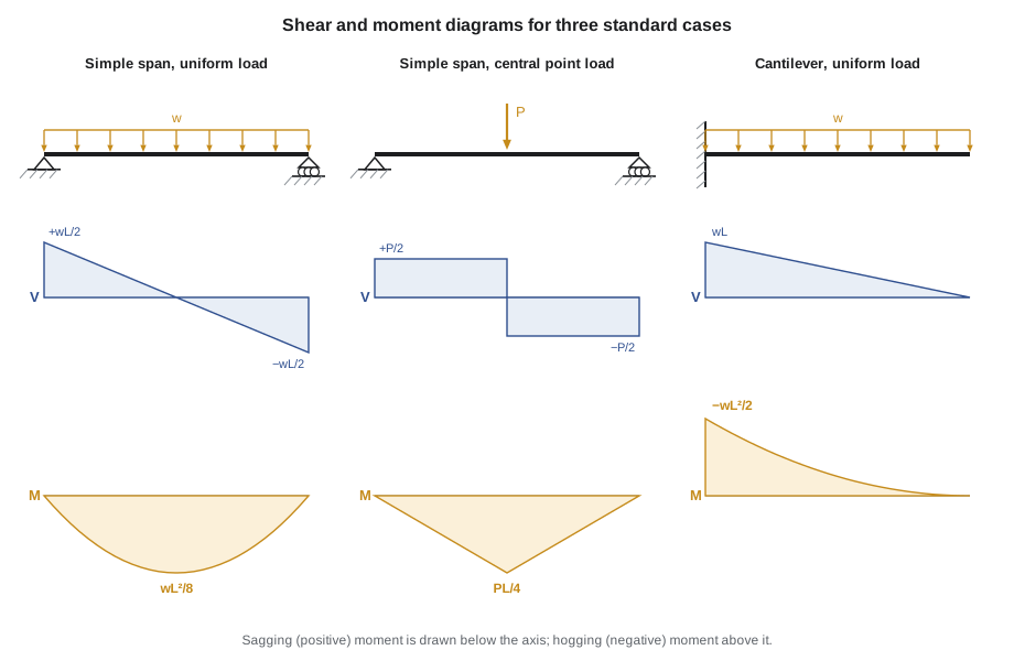
The moment grows with the square of the span in the uniform-load cases. Doubling the span of a beam with the same load per unit length makes the moment four times as large. This is the most important fact in structural design for architects, because it explains why long spans are expensive, why beams get deeper so quickly as spans increase, and why moving a column a little closer can save a surprising amount of structure.
Rules for drawing the diagrams
Shear and moment are related to the load by two simple rules that make sketching the diagrams quick. First, the slope of the shear diagram at any point equals the load intensity there, taken as negative for downward loads: under a uniform load the shear changes steadily, in a straight sloping line, and where there is no load the shear is constant. A point load or reaction makes the shear jump by the size of the force. Second, the slope of the moment diagram equals the shear: where the shear is positive the moment rises, where it is negative the moment falls, and where the shear passes through zero the moment reaches a peak or a trough. The change in moment between two points equals the area under the shear diagram between them.
These rules give a procedure. Find the reactions. Starting at the left end, draw the shear diagram, jumping up or down at each point force and sloping under each distributed load. Then draw the moment diagram, rising and falling according to the area under the shear diagram, with peaks wherever the shear crosses zero. At a free end and at a simple support with no applied moment, the moment is zero, which checks the arithmetic. The maximum moment, the one that sizes the beam, is always at a point where the shear is zero or changes sign.
Overhangs and continuous beams
Beams that run past their supports, or continue over several supports, have both positive and negative moments. Over a support with a cantilever beyond it, the moment is negative: the beam hogs, with its top in tension. In the backspan it changes back to positive, and the point where the moment passes through zero is called a point of inflection. A continuous beam over many equal spans has negative moments over the interior supports and smaller positive moments in the spans than a simply supported beam of the same span would have; for a uniform load on many equal spans, the moments are roughly wL²/10 over the supports and wL²/14 to wL²/16 in the spans. Continuity therefore makes beams stiffer and more efficient, which is why concrete frames and continuous timber purlins are used so widely.
The sign of the moment tells a designer where the tension is, and that has direct architectural consequences. In a reinforced concrete beam, the steel goes at the bottom in the spans and at the top over the supports and in cantilevers. In a timber beam with a notch, a notch on the tension face is dangerous because the wood splits from its corner. In a glass fin or a steel beam with holes for services, openings belong near the neutral axis, at mid-depth, and near points of small moment. A beam whose depth follows its moment diagram, deep at midspan and shallow at the ends, or deep over the supports of a cantilever and tapering to the tip, is both efficient and expressive. Szymańska shows photographs of tapered glulam beams, fish-bellied steel girders and haunched concrete bridges, and asks the students to sketch the moment diagram for each.
# Shear and moment by sections for a glulam floor beam in the wing
span = 7.2                  # (m)
w = 27.4                     # factored uniform load (kN/m)
P, a = 40.0, 2.4             # factored point load from a mezzanine post (kN) at a (m)
RB = (w * span * span / 2 + P * a) / span
RA = w * span + P - RB
def V(x):
    return RA - w * x - (P if x > a else 0)
def M(x):
    return RA * x - w * x * x / 2 - (P * (x - a) if x > a else 0)
n = 720
xs = [span * i / n for i in range(n + 1)]
xm = max(xs, key=M)
print(f"Reactions RA = {RA:.1f} kN, RB = {RB:.1f} kN")
for x, where in [(0, "at A"), (a, "just left of post"), (a + 1e-9, "just right of post"),
                 (span / 2, "midspan"), (xm, "zero shear"), (span, "at B")]:
    print(f"  x = {x:5.2f} m {where:<19} V = {V(x):7.1f} kN   M = {M(x):7.1f} kN m")
print(f"Maximum moment {M(xm):.1f} kN m at x = {xm:.2f} m (shear changes sign there)")
Mu = w * span / 2 * xm - w * xm * xm / 2
print(f"Uniform load alone: wL^2/8 = {w * span ** 2 / 8:.1f} kN m; at x = {xm:.2f} the post load adds {M(xm) - Mu:.1f} kN m")
print(f"With the post moved over a column: maximum moment {w * span ** 2 / 8:.1f} kN m")Reactions RA = 125.3 kN, RB = 112.0 kN x = 0.00 m at A V = 125.3 kN M = 0.0 kN m x = 2.40 m just left of post V = 59.5 kN M = 221.8 kN m x = 2.40 m just right of post V = 19.5 kN M = 221.8 kN m x = 3.60 m midspan V = -13.3 kN M = 225.6 kN m x = 3.11 m zero shear V = 0.1 kN M = 228.8 kN m x = 7.20 m at B V = -112.0 kN M = 0.0 kN m Maximum moment 228.8 kN m at x = 3.11 m (shear changes sign there) Uniform load alone: wL^2/8 = 177.6 kN m; at x = 3.11 the post load adds 54.5 kN m With the post moved over a column: maximum moment 177.6 kN m
The script cuts the beam at hundreds of sections and finds the shear and moment at each, exactly as the free-body method does by hand. The maximum moment occurs where the shear changes sign, which with the post load near the left third of the span is a little to the left of midspan. The point load adds a substantial moment to what the floor alone produces. Callum, who had placed the post for the library's reading mezzanine without thinking about the beam below, moves it to sit directly over a column instead, where it adds no bending at all. The lesson he draws, and that Szymańska wants every student to draw, is that a load placed over a support costs almost nothing, while the same load at midspan costs a great deal.
Worked problem
Shear and moment in the entrance canopy
The canopy beam from Lesson 3 has a backspan of 4 m between its back support A and its front post B, and an overhang of 2 m beyond the post. It carries a factored uniform load of 6 kN/m and a sign of 5 kN at the tip. The reactions were RA = 6.5 kN and RB = 34.5 kN. Find the largest positive and negative moments.
Show solution
- Shear just right of A: +6.5 kN, falling at 6 kN/m.
- The shear reaches zero at 6.5 ÷ 6 = 1.08 m from A; the positive moment peaks there.
- Peak positive moment: 6.5 × 1.08 − 6 × 1.08² ÷ 2 = 7.04 − 3.52 = 3.5 kN·m.
- Moment at the front post, from the overhang side: −(6 × 2² ÷ 2 + 5 × 2) = −(12 + 10) = −22 kN·m.
- The negative moment over the post is about six times the positive moment in the backspan, so the beam must be strongest over the post, with its tension face on top.
- A tapered steel beam, deepest over the post and thin at the tip and at A, would follow the moment diagram.
Answer: The largest moment is the negative moment of about 22 kN·m over the front post; the largest positive moment, in the backspan, is only about 3.5 kN·m.
Shear in beams
Most beams are sized by their moment, but shear matters too. Shear is greatest near the supports, and it is critical in short, heavily loaded beams, in timber beams, where the wood can split along the grain near mid-depth, and in concrete beams, which need stirrups to resist diagonal cracking near their supports. In steel beams, shear is carried mostly by the web, and it governs only in short spans with heavy loads or where the web is cut away. Concentrated reactions also need checking where they enter a beam: a heavy load bearing on a thin steel web can crush or buckle it locally, and stiffener plates are added. In timber, a notch at the bottom of a beam end, where shear is high, is one of the most common causes of failure, and the material standards strictly limit such notches.
Reading structure in moment diagrams
Szymańska ends the class by asking each student to draw the moment diagram for a structural idea from their Design Studio III project. Wren's cantilevered reading room over the library entrance turns out to have a moment at its root larger than any other in her building, carried by a pair of beams she had drawn as shallow as the floor. Joon-ho's long, column-free daycare playroom has a midspan moment four times what he expected, because he had doubled the span to remove one column. Ingrid's continuous timber purlins over the hall's trusses have small, alternating moments, and she discovers she can make them shallower than she had drawn. 'You do not need to calculate every beam,' Szymańska says. 'You need to know where the big moments are, and to put depth there.'
Exercise 6: shear and moment
- Draw the shear and moment diagrams for the three standard cases, with their peak values in terms of w, P and L.
- Draw the diagrams for a beam in your studio project with at least one overhang, and find the inflection point.
- Calculate how the maximum moment of a uniformly loaded beam changes if its span grows by a quarter.
- Sketch a beam whose depth follows its moment diagram, and explain where you would put any holes for services.
Self-check
- Does my moment diagram return to zero at free ends and simple supports?
- Is my maximum moment at a point where the shear is zero or changes sign?
- Do I know which face of each beam is in tension?
Common mistakes
MistakeTaking the maximum moment of a uniform load as wL²/4.
InsteadUse wL²/8 for a uniform load and PL/4 for a central point load.
MistakeForgetting that moment grows with the square of the span.
InsteadExpect four times the moment when the span doubles under the same load per length.
MistakeIgnoring the negative moment over a support with an overhang.
InsteadCheck the moment at every support with a cantilever, and put strength on the tension face.
MistakePlacing heavy point loads at midspan without need.
InsteadPlace them over columns or near supports where they add little bending.
MistakeCutting notches or holes where shear or moment is large.
InsteadKeep openings near mid-depth and near points of small moment, and avoid notches at beam ends.
Summary and key terms
- At any section, a beam carries a shear force and a bending moment that balance the forces on either side.
- Simply supported beams have peak moments of wL²/8 under uniform load and PL/4 under a central point load; cantilevers have support moments of wL²/2 and PL.
- The slope of the shear diagram equals the load, and the slope of the moment diagram equals the shear, so maximum moments occur where the shear is zero.
- Overhangs and continuous beams create negative moments over supports, with the tension on top.
- Moment grows with the square of the span, which explains why long spans need so much more depth and material.
- Shear force
- The sum of vertical forces on one side of a section of a beam.
- Bending moment
- The sum of moments about a section of the forces on one side of it.
- Sagging
- Positive bending that compresses the top of a beam and stretches the bottom.
- Hogging
- Negative bending that stretches the top of a beam and compresses the bottom.
- Point of inflection
- A point where the bending moment changes sign.
- Continuous beam
- A beam that runs unbroken over more than two supports.
Practice problems
Work each problem on paper first, then reveal the answer to check.
What is the maximum moment in a simply supported beam of span 6 m with a uniform load of 10 kN/m?
Show answer
10 × 6² ÷ 8 = 45 kN·m.
The span in the previous question increases to 7.5 m. What is the new maximum moment?
Show answer
10 × 7.5² ÷ 8 = 70.3 kN·m, about 1.56 times as much for a span only 1.25 times as long.
A simply supported beam of span 5 m carries a point load of 24 kN at midspan. What is the maximum moment?
Show answer
24 × 5 ÷ 4 = 30 kN·m.
Where is the steel placed in a concrete cantilever balcony, and why?
Show answer
At the top, because the cantilever's negative moment puts the top face in tension.
Why does the maximum moment occur where the shear is zero?
Show answer
Because the slope of the moment diagram equals the shear, so the moment stops rising where the shear reaches zero.
Lesson quiz · 5 questions
Score 60% or more to complete this lesson.
Create a free account to save your progress, take quizzes and earn a certificate.