
ARCH-230 · Lesson 12 of 12 · 21 min
Structural form and design
For the last class Szymańska brings back the chain she hung across the classroom in the first week. This time she hangs small weights from it at equal spacing along its length, and the chain changes from its smooth droop into a gentler curve, almost a parabola. She photographs it and flips the image upside down on the screen: an arch. Then she moves the weights so that most of them hang near one end, and the chain's shape becomes lopsided; flipped, it is an arch that leans. 'Every load pattern has a shape that carries it in pure tension or pure compression,' she says. 'Beams and trusses fight their loads with bending and with triangles. Cables and arches find a shape and let the loads flow. Today we put the whole course together by asking what shape a structure should be.'
Form-active structures
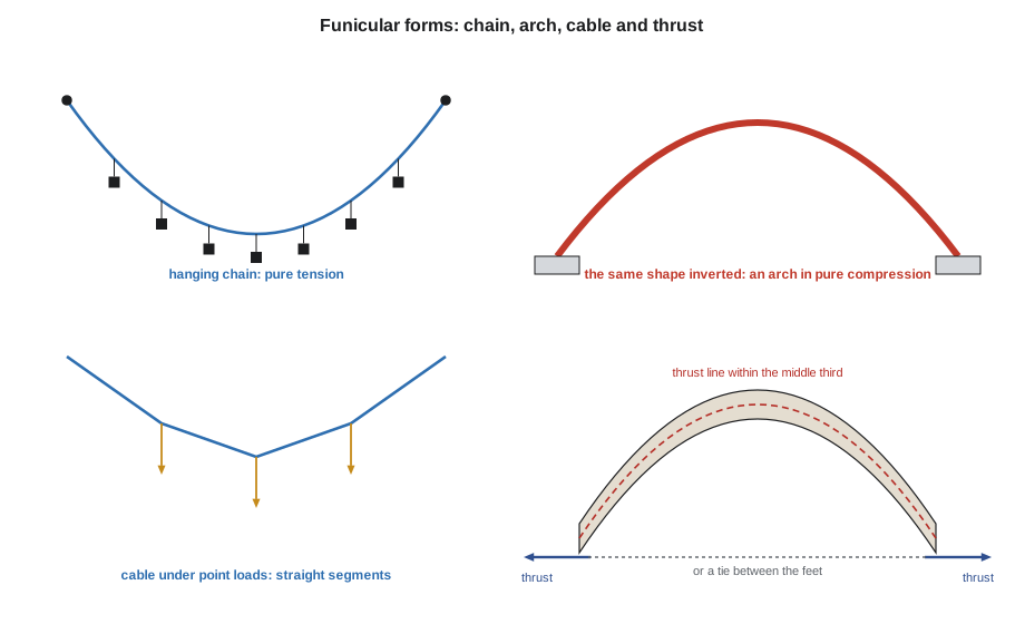
The structures in Lessons 4 to 11 carry loads mainly by bending or by triangulation, and their shapes are largely independent of the loads: a beam is straight whatever it carries. Another family of structures carries loads by its shape. A cable hung between two supports carries a load in pure tension by sagging into the shape that matches the load. An arch, which is that cable's shape turned upside down, carries the same load in pure compression. Shells, vaults and domes are surfaces that do the same in two directions, and tensioned membranes and cable nets are their tension counterparts. These form-active structures can span great distances with very little material, because every part of their section is evenly stressed and there is little or no bending.
The shape that carries a given set of loads in pure tension or compression is called the funicular shape, from the Latin for rope. For a cable carrying only its own weight, it is the catenary, the curve of a hanging chain. For a cable carrying a load spread evenly along its horizontal span, such as a bridge deck hung from it, it is a parabola. For a cable carrying a few point loads, it is a series of straight segments, changing direction at each load. When the load changes, the funicular shape changes: a cable simply moves into its new shape, but an arch cannot, so it must resist the difference by bending. Real arches are therefore funicular for their main, permanent load and stiff enough in bending to handle the rest, such as uneven snow or wind.
Cables and arches
A parabolic cable of span L and sag f carrying a uniform load w has a horizontal tension H at every point along its length, equal to the beam moment wL²/8 divided by the sag. This is the hanging sign of Lesson 1 in another form, and it gives the same warning: the shallower the cable, the larger its tension. The vertical reactions at the supports are wL/2 each, like a beam's, and the maximum tension, at the supports, combines the horizontal and vertical components.
An arch of the same span and rise carries the same uniform load with the same horizontal force, now a thrust, pushing outward on its supports. The thrust is the price of an arch: it must be resisted by heavy abutments, by buttresses, by the ground, or by a tie between the two bases that turns the arch and tie into a self-contained structure, like a bow and its string. Many arched roofs, from nineteenth-century railway stations to contemporary glulam arenas, are tied, so that their supporting walls carry only vertical loads. A tall arch, with a large rise for its span, has a small thrust; a shallow one, a large thrust. Engineers often use rise-to-span ratios of about one fifth to one eighth for arches and sag-to-span ratios of about one eighth to one twelfth for cables.
Masonry arches add a further rule. Masonry is strong in compression but cannot resist tension at its joints, so the line of thrust, the path of the resultant compressive force through the arch, must stay within the arch's thickness, and to keep every joint fully compressed, within its middle third. The masonry builders of Roman bridges and Gothic cathedrals knew this through experience; the nineteenth century turned it into theory, and modern engineers still use the same thrust-line reasoning to assess historic structures.
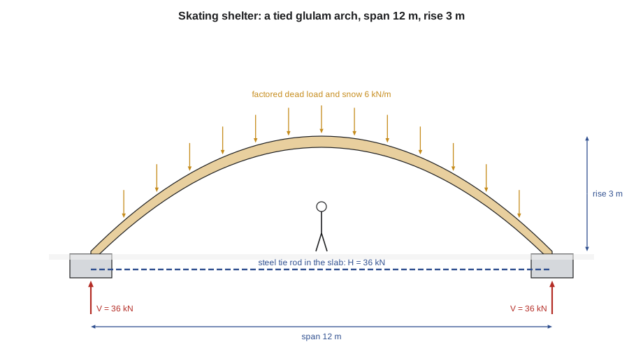
# A tied glulam arch for a covered skating shelter beside the warming hut
import math
L = 12.0                       # span (m)
w = 6.0                       # factored uniform load: dead load plus snow (kN/m)
print("Rise   rise/span   thrust H   vertical V   max force in arch")
for f in (1.5, 2.0, 3.0, 4.0, 6.0):
    H = w * L ** 2 / (8 * f)
    V = w * L / 2
    T = math.hypot(H, V)
    print(f"{f:5.1f} m   1/{L / f:4.1f}   {H:8.1f} kN   {V:8.1f} kN   {T:8.1f} kN")
f = 3.0
H = w * L ** 2 / (8 * f)
A_tie = H * 1000 / (0.9 * 350)
print(f"Chosen rise {f} m: steel tie needs {A_tie:.0f} mm2 of gross area")
# A parabola and a catenary of the same span and sag are nearly the same shape when the sag is small
lo, hi = 0.05 * L, 100 * L      # bisection for the catenary parameter a with sag f
for _ in range(200):
    a = (lo + hi) / 2
    if a * (math.cosh(L / (2 * a)) - 1) > f:
        lo = a
    else:
        hi = a
for x in (L / 4, L / 8):
    par = f * (1 - (2 * (x - L / 2) / L) ** 2)
    cat = f - a * (math.cosh((x - L / 2) / a) - 1)
print(f"Height at {x:.2f} m from a support: parabola {par:.3f}, catenary {cat:.3f} m")Rise rise/span thrust H vertical V max force in arch 1.5 m 1/ 8.0 72.0 kN 36.0 kN 80.5 kN 2.0 m 1/ 6.0 54.0 kN 36.0 kN 64.9 kN 3.0 m 1/ 4.0 36.0 kN 36.0 kN 50.9 kN 4.0 m 1/ 3.0 27.0 kN 36.0 kN 45.0 kN 6.0 m 1/ 2.0 18.0 kN 36.0 kN 40.2 kN Chosen rise 3.0 m: steel tie needs 114 mm2 of gross area Height at 3.00 m from a support: parabola 2.250, catenary 2.289 m Height at 1.50 m from a support: parabola 1.312, catenary 1.364 m
The table shows the trade between height and thrust. At a rise of 1.5 m, one eighth of the span, the thrust is 72 kN; at 3 m, one quarter of the span, it halves to 36 kN; at 6 m, a semicircle's height, it halves again. Ingrid, who is designing the shelter as her final exercise, chooses a rise of a quarter of the span, which gives generous headroom down the middle of the shelter and a moderate thrust, and a steel tie rod buried in the concrete slab between the arch's feet. The comparison at the end of the script shows why Galileo believed that a hanging chain formed a parabola: for shallow curves the parabola and the catenary are almost indistinguishable, and the difference between them was proved only later in the seventeenth century. For a builder either curve will do.
Choosing a structural system
Structural form follows span. Each system has a range of spans in which it is efficient, and moving outside that range costs material, depth or both. The table below, which Szymańska calls the most useful page of the course, summarizes typical spans and depths for the systems the students have met in Lessons 4 to 11.
| System | Efficient spans | Typical depth |
|---|---|---|
| Wood joists and rafters | up to about 6 m | span / 20 |
| CLT panels | 3 to 8 m | span / 30 |
| Glulam and steel beams | 6 to 18 m | span / 15 to span / 24 |
| Concrete flat slabs | 6 to 10 m | span / 30 |
| Open-web steel joists | 10 to 40 m | span / 20 |
| Steel and timber trusses | 15 to 60 m | span / 10 to span / 15 |
| Arches and vaults | 20 to 100 m or more | rise about span / 5 to span / 8 |
| Cable and membrane roofs | 50 to 200 m or more | sag about span / 8 to span / 12 |
Span is only the first question. Szymańska gives the students a list of others, in roughly the order an engineer asks them. What loads must the structure carry, and how much do they vary? Must the structure resist lateral loads, or will something else? How high may it be, and what may it weigh? What will it cost, how fast can it be built, and by whom? What fire resistance, acoustic separation and vibration performance does it need? How much carbon will it embody, and can it be taken apart and reused? And, last but not least, what should the space feel like? A good structural concept answers all of these at once, and the architect's role is to keep the last question in the conversation while the engineer works on the others.
Structure and architecture
The history of architecture is full of buildings whose form is their structure. Gothic cathedrals made their vaults soar on flying buttresses that carried the thrust outside the walls. Nineteenth-century railway stations spanned great sheds on iron arches and trusses. In the twentieth century, Félix Candela built thin concrete shells in Mexico shaped as hyperbolic paraboloids, surfaces that can be formed from straight boards yet curve in two directions; Eladio Dieste in Uruguay built long, rippling brick vaults, reinforced with a little steel, that were cheap and beautiful; and Frei Otto's cable-net roofs for the Munich Olympic Park in 1972 floated over the stadiums like tents. Closer to home, the geodesic dome that Buckminster Fuller designed for the United States pavilion at Expo 67 in Montreal, now the Biosphère, enclosed an enormous volume with a lattice of light steel tubes, and the timber roofs of prairie arenas and farm buildings show a vernacular of trusses and arches built to carry heavy snow.
What these works share is not a particular style but a clear relationship between load, form and material. Szymańska warns against two opposite failures. One is structure as decoration, shapes that look structural but are not, with the real structure hidden inside and fighting the visible form. The other is structure as afterthought, a design drawn without regard to how it stands, later filled with whatever beams and columns make it work. Between them lies the approach she hopes the students will take into the next structures course and into practice: to treat the structure as one of the first ideas of a design, to understand roughly how it works, and to give it the depth, spacing and continuity it needs from the start.
Worked problem
A structural concept for the hub, in numbers
At the end of the course, Callum writes a one-page structural concept for the community hub from Design Studio III, summarizing the numbers the class has calculated. What does it contain?
Show solution
- Loads: roof dead load about 1.2 kPa, snow 1.72 kPa; library floor dead load 2.78 kPa and live load 2.9 kPa (Lesson 2).
- Wing: CLT panels on glulam beams 175 by 570 mm spanning 7.2 m (Lesson 7), on glulam columns 215 by 228 mm carrying about 560 kN (Lessons 8 and 9).
- Hall: eight-panel Pratt trusses of glulam, 2 m deep, at 6 m centres, with chord forces of about 760 kN (Lesson 4).
- Commons: a slender steel column braced at the mezzanine to carry 400 kN (Lesson 8).
- Lateral system: roof and floor diaphragms carrying wind to tension-only braced bays at the hall's corners and at the wing's cores and west wall (Lessons 9 and 11).
- Foundations: pile caps with two piles under each interior wing column, more under the hall's trusses, on the site's soft clay (Lesson 9).
- Open questions for the engineer: floor vibration in the library, the hall truss connections, fire protection of steel and connections, and the thermal break at the canopy.
Answer: A single page that states the loads, the systems, the key member sizes and the open questions gives the engineer a clear starting point and shows that the architecture already stands.
Exercise 12: structural design
- Design a covered shelter or canopy using a form-active structure, a cable, an arch or a shell, and find its funicular shape for its main load by hanging a chain model.
- Calculate the thrust or tension in your structure and show how it is resisted, by abutments, a tie or anchors.
- Write a one-page structural concept for your Design Studio III project, listing loads, systems, key member sizes, lateral system and foundations.
- Make a model of your project's structure alone, without walls or finishes, and test it with weights and a sideways push.
- Present your structure to a classmate playing the engineer, and record the three questions they ask.
Self-check
- Does the form of my structure suit its main load, and how does it handle the other loads?
- Have I shown where every thrust and every tension goes?
- Can I explain in one paragraph how my building stands up, in both directions?
Common mistakes
MistakeDrawing a shallow arch or flat cable without accounting for its large horizontal force.
InsteadCalculate the thrust or tension, and show the abutment, tie or anchor that resists it.
MistakeAssuming an arch is funicular for every load.
InsteadGive arches enough bending stiffness for uneven snow, wind and point loads.
MistakeChoosing a structural system outside its efficient span range.
InsteadUse the span table to choose a system that suits the span, then refine.
MistakeMaking a structural shape decorative while hiding the real structure.
InsteadLet the visible form be the working structure, or be honest that it is not.
MistakeLeaving the structure until the design is finished.
InsteadMake the structure one of the first ideas, and develop it with the engineer.
Summary and key terms
- Form-active structures, such as cables, arches, shells and membranes, carry load by their shape, with little bending.
- The funicular shape for a load is the shape a hanging chain takes under it; inverted, it is the shape of an arch in pure compression.
- A cable or arch carrying a uniform load has a horizontal force of wL²/8f, so shallow forms produce large tensions and thrusts that must be resisted by anchors, abutments or ties.
- Each structural system has a range of efficient spans and typical depths, which guide early design.
- Good architecture makes structure an early, clear and honest part of the design.
- Funicular
- The shape that carries a given load in pure tension or compression.
- Catenary
- The curve of a hanging chain under its own weight.
- Thrust
- The horizontal outward force an arch exerts on its supports.
- Tie
- A tension member that resists the thrust of an arch between its supports.
- Thrust line
- The path of the resultant compressive force through an arch or vault.
- Shell
- A thin, curved surface structure that carries load mainly by membrane forces.
Practice problems
Work each problem on paper first, then reveal the answer to check.
A cable spans 30 m with a sag of 3 m and carries a uniform load of 2 kN/m. What is its horizontal tension?
Show answer
2 × 30² ÷ (8 × 3) = 75 kN.
If the sag in the previous question is halved, what happens to the horizontal tension?
Show answer
It doubles.
Why are many arched roofs tied?
Show answer
The tie resists the arch's outward thrust, so the supports carry only vertical loads.
Where must the thrust line lie in a masonry arch for every joint to stay in compression?
Show answer
Within the middle third of the arch's thickness.
What structural system suits a span of 40 m for a sports hall roof?
Show answer
A steel or timber truss, an open-web joist system or an arch; beams of solid section would be very deep.
Lesson quiz · 5 questions
Score 60% or more to complete this lesson.
Create a free account to save your progress, take quizzes and earn a certificate.