
ARCH-230 · Lesson 7 of 12 · 22 min
Beam sizing
Szymańska hands each student a plain wooden ruler and asks them to lay it flat across two books and press on the middle. It bends easily. Then she asks them to turn it on its edge and press again. It barely moves. 'Same ruler, same material, same span,' she says. 'Lying flat, it is about thirty times thinner in the direction it bends than when it stands on edge. Standing up, it is roughly thirty times stronger and nearly a thousand times stiffer. Today you learn why, and how to choose a beam that is just deep enough.'
Bending stress
Lesson 6 showed that a beam carries a bending moment at every section, and the foam beam showed that bending squeezes one side and stretches the other. Somewhere between the two faces is a surface that neither shortens nor lengthens: the neutral axis. In a symmetrical beam it lies at mid-depth. The strain in the beam grows in proportion to the distance from the neutral axis, and in the elastic range so does the stress, which is greatest at the top and bottom faces. The resultant of the compressive stresses on one side and the tensile stresses on the other forms a couple whose moment balances the bending moment at the section.
The relationship between the moment and the stress is the flexure formula. The stress at a distance y from the neutral axis equals the moment times y divided by the moment of inertia of the section, I, a geometric property that measures how far the material lies from the neutral axis. At the extreme fibres, where y is greatest, the stress is the moment divided by the section modulus, S, which is I divided by the distance to the extreme fibre.
For a rectangle of width b and depth h, these properties have simple formulas. The moment of inertia grows with the cube of the depth and the section modulus with its square. Width enters only to the first power.
This explains the ruler. Doubling a beam's depth makes it four times as strong in bending and eight times as stiff; doubling its width makes it only twice as strong and twice as stiff. Deep, narrow beams are therefore much more efficient than shallow, wide ones, as long as they are braced against twisting sideways. The same logic produced the I-shape of steel beams: by putting most of the material in two flanges far from the neutral axis, joined by a thin web, an I-beam gets a large moment of inertia from little material. Hollow tubes and box beams follow the same principle.
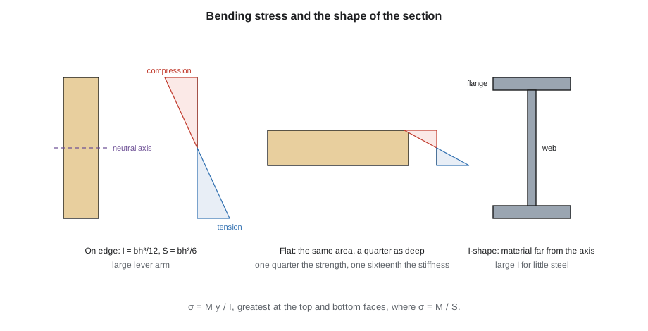
Strength: choosing a section
Designing a beam for strength means choosing a section whose factored bending resistance is at least the factored moment. In limit states design, the resistance is the material's specified strength in bending, reduced by its resistance factor and by any other factors the material standard requires, multiplied by the section modulus. Rearranged, this gives the section modulus the beam needs.
For wood, CSA O86, Engineering Design in Wood, sets the specified bending strength for each species and grade and adjusts it for load duration, service condition, size and lateral stability; its current edition is CSA O86:24. For a common spruce-pine glulam grade, 20f-EX, the specified bending strength is 25.6 MPa and φ is 0.9. For steel, CSA S16, Design of Steel Structures, now in its 2024 edition, gives the bending resistance of a laterally braced compact beam as φ Z Fy, where Z is the plastic section modulus, which accounts for the whole section yielding, and φ is 0.9. A steel beam's plastic modulus is typically about 10 to 15 hundredths larger than its elastic section modulus, which is part of steel's reserve of strength.
Strength in bending is not the only strength check. Shear, as Lesson 6 explained, can govern short or heavily loaded beams, especially in timber; for a rectangular section the largest shear stress, at mid-depth, is 1.5 times the average, V divided by the area. Bearing at the supports must be checked, as Lesson 5 showed for wood across the grain. And a beam whose compression edge is not braced can buckle sideways and twist at a load well below its bending strength, a failure called lateral-torsional buckling. A floor deck nailed or screwed to the top of a beam usually braces it fully; a beam with nothing attached along its compression edge, such as a long roof beam under wind uplift or a cantilever's bottom flange, needs separate bracing or a larger section.
Stiffness: limiting deflection
A beam that is strong enough may still sag too much. Excessive deflection cracks plaster and tile, jams doors and windows, makes floors bounce and roofs pond, and looks wrong. Deflection is checked under service loads, without load factors, using the beam's stiffness, E times I. For a simply supported beam under a uniform load, the midspan deflection is given by a standard formula; for a central point load, by another.
The span appears to the fourth power. A beam with the same load per unit length but a span one quarter longer deflects about 2.4 times as much. This is why stiffness, not strength, usually governs long and lightly loaded beams, and why wood, with its low modulus, often needs more depth than its strength alone would suggest. Codes and standards set deflection limits as fractions of the span. Common limits are L/360 under live load for floors with brittle finishes, L/240 under total load, and L/180 or more lenient for roofs without ceilings. For wood and concrete, long-term loads also cause creep, a slow additional deflection that can double the initial sag from dead load over years; engineers allow for it by increasing the calculated dead load deflection.
Floors also have to feel solid. A long, light floor can be strong and meet its deflection limits but still bounce when people walk across it. For timber and steel floors, engineers check the floor's natural frequency or its deflection under a single footstep. Szymańska's rule of thumb is that floors people walk on every day should feel heavier than the calculations require, and that the floors of a library or daycare are worth a little extra stiffness.
# Size the glulam floor beam in the wing, then compare a steel beam
span = 7.2                                   # (m)
wf = 27.4                                    # factored load (kN/m)
wD, wL = 9.73, 10.15                          # service dead and live loads (kN/m)
Mf = wf * span ** 2 / 8                      # (kN m)
Fb, E, phi = 25.6, 10300, 0.9                # glulam bending strength and modulus (MPa)
S_req = Mf * 1000000.0 / (phi * Fb)
I_live = 5 * wL * 1 * (span * 1000) ** 4 / (384 * E * span * 1000 / 360)
I_tot = 5 * (wD + wL) * 1 * (span * 1000) ** 4 / (384 * E * span * 1000 / 240)
print(f"Factored moment {Mf:.1f} kN m; required S = {S_req:,.0f} mm3")
print(f"Required I for L/360 live: {I_live:,.0f} mm4; for L/240 total: {I_tot:,.0f} mm4")
b, lam = 175, 38                          # glulam width and lamination thickness (mm)
n = 6
while True:
    h = n * lam
    S, I = b * h * h / 6, b * h ** 3 / 12
    if S >= S_req and I >= max(I_live, I_tot):
        break
    n += 1
gov = "deflection" if b * h * h / 6 > S_req * 1.05 else "strength"
print(f"Glulam {b} x {h:g} mm ({n} laminations): S = {S:,.0f}, I = {I:,.0f}; governed by {gov}")
print(f"  span-to-depth ratio {span * 1000 / h:.1f}")

# Steel W shapes, laterally braced by the deck: (name, depth, Z, Ix)
shapes = [('W310x39', 310, 610000.0, 85100000.0), ('W360x39', 353, 667000.0, 102000000.0), ('W310x45', 313, 711000.0, 99200000.0), ('W360x45', 352, 784000.0, 122000000.0), ('W410x46', 403, 885000.0, 156000000.0)]
Fy, Es = 350, 200000
Z_req = Mf * 1000000.0 / (0.9 * Fy)
I_s = max(I_live, I_tot) * E / Es
for name, d, Z, I in shapes:
    if Z >= Z_req and I >= I_s:
        print(f"Steel: need Z = {Z_req:,.0f} and I = {I_s:,.0f}; lightest adequate {name}, about {d} mm deep")
breakFactored moment 177.6 kN m; required S = 7,706,250 mm3 Required I for L/360 live: 1,724,120,388 mm4; for L/240 total: 2,251,265,243 mm4 Glulam 175 x 570 mm (15 laminations): S = 9,476,250, I = 2,700,731,250; governed by deflection span-to-depth ratio 12.6 Steel: need Z = 563,657 and I = 115,940,160; lightest adequate W360x45, about 352 mm deep
The script finds the glulam depth from both strength and stiffness. For this beam the depth needed for strength alone would be about 514 mm, but the total-load deflection limit asks for a little more, so stiffness governs and the beam ends up 175 by 570 mm, fifteen laminations deep. The steel alternative, laterally braced by the CLT deck, is a W360×45, about 350 mm deep: shallower, as expected, because steel is so much stiffer, though it would need fire protection or encasement, and its connection to the timber deck and columns adds detail. Callum keeps the glulam beam. Its depth fits the section he drew in Design Studio III, which had allowed a span-to-depth ratio of about 18; the actual ratio comes out close to 13, so he deepens the floor zone in his section by about 170 mm and notes that the decision to keep the concrete topping for acoustics is now costing beam depth too.
| Standard sizes | Glulam | Steel W shapes |
|---|---|---|
| Widths | 80, 130, 175, 215, 265 mm and wider | Flange widths set by the rolled section |
| Depths | In multiples of 38 mm laminations | Nominal depths of 150 to 1,100 mm |
| Typical span-to-depth | About 15 to 20 for floors | About 20 to 24 for floors |
| Names | Width by depth | W followed by nominal depth in millimetres and mass in kg/m, such as W360×39 |
Worked problem
A deep beam or a wide one
Joon-ho wants a column-free daycare playroom and proposes to remove a column, so that a glulam beam spans 10.8 m instead of 7.2 m. Under the same load per unit length, how much larger are the moment and the deflection, and roughly how much deeper must the beam be if its width stays the same?
Show solution
- Moment grows with the square of the span: (10.8 ÷ 7.2)² = 1.5² = 2.25 times as large.
- Deflection grows with the fourth power: 1.5⁴ = 5.06 times as large for the same section.
- The deflection limit L/360 grows only in proportion to the span, by 1.5 times, so the required moment of inertia grows by 5.06 ÷ 1.5 = 3.4 times, which is 1.5³.
- For the same width, I grows with the cube of the depth, so the depth must grow by the cube root of 3.4, which is 1.5 times: from 570 mm to about 855 mm.
- The required S grows by 2.25 times, which for the same width needs a depth 1.5 times as great too, so both checks point to the same answer.
- The beam would be about 875 mm deep, twenty-three laminations, which pushes the floor-to-floor height up or the ceiling down along the whole wing.
Answer: The moment grows 2.25 times and the deflection about five times; the beam must be about 1.5 times as deep, roughly 875 mm, unless another column or a different system is used.
Beams as architecture
Beam sizing is where architects meet structure most often. Every floor-to-floor height, ceiling height and roof profile depends on beam depths, and the early rules of thumb from Design Studio III are only as good as the spans and loads assumed. Szymańska urges the students to treat the beam schedule as a design tool. Small changes in the grid, such as making bays a little shorter in the direction of the beams, or arranging beams to span the short way of a bay, can save a great deal of depth. Continuous beams and beams with fixed ends deflect much less than simply supported ones. Composite floors, in which concrete is connected to steel or timber beams so that they act together, gain stiffness for little extra depth. And where a beam is exposed, its depth, its spacing and the way it meets its column or wall become part of the room's character.
Szymańska also warns against designing beams to the minimum. A floor beam sized exactly to its deflection limit will be unpleasantly lively, a roof beam sized exactly for strength leaves no room for added rooftop equipment, and any beam sized without allowance for services passing through or below it will cause trouble on site. 'Size the beam,' she says, 'then give it a little more depth than the calculation says. The client will never thank you for the extra fifty millimetres, but they will never forgive you for a bouncy floor.'
Exercise 7: beam sizing
- Calculate I and S for three rectangular sections of the same area but different proportions, and compare their bending strength and stiffness.
- Size a glulam floor beam for your studio project for both strength and deflection, and say which governs.
- Select a steel W shape for the same beam and compare its depth, weight and fire protection needs with the glulam beam.
- Find the span at which deflection, rather than strength, begins to govern for your floor beams.
- Draw a section through your floor showing the beam at its real depth, with ceilings and services.
Self-check
- Did I check deflection with service loads and strength with factored loads?
- Is the compression edge of my beam braced?
- Have I allowed depth for services, fire protection and finishes below the beam?
Common mistakes
MistakeUsing factored loads to check deflection.
InsteadCheck deflection with unfactored service loads.
MistakeMaking beams wider instead of deeper.
InsteadAdd depth first; strength grows with depth squared and stiffness with depth cubed.
MistakeIgnoring the fourth-power effect of span on deflection.
InsteadExpect a beam on a longer span to need much more stiffness, not just more strength.
MistakeAssuming a beam is braced when nothing is attached along its compression edge.
InsteadCheck lateral-torsional buckling or add bracing.
MistakeSizing a floor exactly to its deflection limit.
InsteadLeave a margin for vibration, creep and future changes.
Summary and key terms
- Bending stress varies linearly from the neutral axis and is greatest at the extreme fibres, where it equals M divided by S.
- For a rectangle, I = bh³/12 and S = bh²/6, so depth is far more effective than width.
- A beam is sized for strength by requiring its factored resistance, φ Fb S for wood or φ Z Fy for steel, to equal or exceed the factored moment.
- Deflection is checked under service loads; it grows with the fourth power of the span and is limited to fractions such as L/360.
- Stiffness often governs timber beams and long spans; beam depth is an architectural decision that affects heights, services and character.
- Neutral axis
- The line in a beam section where bending causes no stress.
- Moment of inertia
- A section property measuring how far its area lies from the neutral axis; governs stiffness.
- Section modulus
- The moment of inertia divided by the distance to the extreme fibre; governs elastic bending strength.
- Plastic section modulus
- A section property used for steel beams, based on the whole section yielding.
- Deflection
- The movement of a beam under load, usually its sag at midspan.
- Lateral-torsional buckling
- Sideways buckling and twisting of a beam whose compression edge is unbraced.
Practice problems
Work each problem on paper first, then reveal the answer to check.
What are I and S for a rectangular beam 100 mm wide and 300 mm deep?
Show answer
I = 100 × 300³ ÷ 12 = 225 × 10⁶ mm⁴; S = 100 × 300² ÷ 6 = 1.5 × 10⁶ mm³.
By how much do the strength and stiffness of that beam change if it is made twice as deep?
Show answer
Strength in bending grows four times and stiffness eight times.
A beam carries a factored moment of 90 kN·m. With φFb of 23 MPa, what section modulus does it need?
Show answer
90 × 10⁶ ÷ 23 = 3.9 × 10⁶ mm³.
What is the L/360 deflection limit for a beam spanning 6 m?
Show answer
6,000 ÷ 360 = 16.7 mm.
Why does stiffness often govern timber beams?
Show answer
Wood's modulus of elasticity is low, so a timber beam sized for strength may still deflect too much.
Lesson quiz · 5 questions
Score 60% or more to complete this lesson.
Create a free account to save your progress, take quizzes and earn a certificate.