
ARCH-110 · Lesson 5 of 12 · 20 min
Axonometric drawing
Joon-ho has drawn the boathouse in plan, section and elevation, and the drawings are correct, but when his grandmother looks at them she asks what it will look like. He tries to explain how the three views fit together and gives up. Professor Visser shows him a different drawing: the plan of the boathouse rotated on the board, with its walls rising straight up from it, the roof sitting on top and the bank and river spreading underneath. 'This is an axonometric,' she says. 'You can measure it like a plan, and your grandmother can read it like a picture. It shows the whole building at once, from above, as no one will ever see it, and that is its strength.'
What axonometric drawing is
An axonometric is a parallel projection in which the object is tilted or rotated so that three faces are visible at once: typically the top and two sides. Like plans, sections and elevations, axonometrics use parallel projection lines, so there is no vanishing point and parallel edges stay parallel. Unlike orthographic views, the object is not square to the picture, so the three principal axes of the building, its width, depth and height, all appear in the drawing. Lengths along the three axes can be measured, sometimes at true scale and sometimes at a fixed reduction, which is what makes axonometrics so useful: they are pictures you can measure.
Axonometrics and their relatives became central to architectural representation in two waves. Auguste Choisy's history of architecture, published in 1899, used worm's-eye axonometrics that showed plan, section and structure at once. In the 1920s, the De Stijl artists and the Bauhaus used axonometrics to present abstract spatial compositions, and modern architects have used them ever since to explain how buildings are put together.
The family of parallel projections
Axonometrics are classified by the angles the three axes make on the page, and by whether lengths along each axis are drawn at true scale.
- Isometric: all three axes are equally foreshortened, and on the page they are 120 degrees apart, with the vertical axis upright and the other two at 30 degrees above horizontal. In drafting practice all three axes are usually drawn at full scale, which makes the drawing a little larger than a true isometric projection but much easier to construct.
- Dimetric: two axes are equally foreshortened and the third differs; for example, the vertical at full scale and the two horizontals at different angles.
- Trimetric: all three axes are foreshortened differently; rarely constructed by hand but easy in software.
- Plan oblique, often called a plan axonometric or military projection: the plan is drawn at true shape and size, rotated on the page, commonly at 45/45 or 30/60 degrees, and verticals are projected straight up. Every horizontal plane, such as a floor or roof, appears at its true shape.
- Elevation oblique, or cavalier projection: the elevation is drawn at true shape and depth is projected back at an angle, often 45 degrees, sometimes at full length (cavalier) or half length (cabinet).
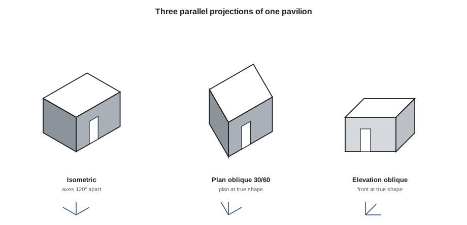
Constructing a plan oblique
The plan oblique is the architect's favourite axonometric because it starts from a drawing you already have. Rotate the plan on the board, typically so that its main walls run at 30 and 60 degrees, or at 45 and 45 degrees, to the horizontal. Then draw verticals straight up from every corner, measured at the same scale as the plan, and connect their tops. Because the plan is undistorted, circles in plan stay circles, angles in plan stay true, and floor patterns can be traced directly.
The angle of rotation changes the emphasis. At 45/45, both walls are given equal weight but the drawing can look as if it is falling over, because vertical edges at the front and back corners line up. At 30/60, one face is emphasized and the other is seen more steeply; this is usually the more natural view. Vertical lengths can be reduced, for example to three quarters, to correct the stretched appearance a plan oblique sometimes has, but full-height verticals are easier and more common.
A plan oblique is also a perfect base for cutaways. Draw the walls rising only to a cut height, say 1.2 m (4 ft) above the floor, and you have a three-dimensional plan that shows rooms, openings and furniture. Lift off the roof, or draw it in dashed outline, and the interior is revealed.
Constructing an isometric
For an isometric, draw a vertical axis and two axes at 30 degrees above horizontal, left and right. Measure the building's width along one sloping axis, its depth along the other and its height on the vertical, all at the same scale. Lines parallel to the axes, called isometric lines, can be measured; lines not parallel to an axis, such as the slope of a roof or a diagonal wall, cannot be measured directly and must be found by plotting their end points along isometric lines. Circles in an isometric appear as ellipses, which you can construct by the four-centre method or draw with an isometric ellipse template.
The isometric gives the most balanced view of a box-shaped object, with no face favoured, which is why it is common in product design, engineering and assembly diagrams. In architecture it can look slightly mechanical, and the distorted plan makes it less useful for showing room layouts than a plan oblique.
# Project 3-D points (x, y, z) onto the page in isometric and plan oblique
import math
def iso(x, y, z):
    a = math.radians(30)
    return ((x - y) * math.cos(a), (x + y) * math.sin(a) + z)
def plan_oblique(x, y, z, rot=30):
    r = math.radians(rot)
    return (x * math.cos(r) - y * math.sin(r), x * math.sin(r) + y * math.cos(r) + z)
w, d, h = 4000, 3000, 2700                     # pavilion width, depth and height
corners = [(0, 0, 0), (w, 0, 0), (w, d, 0), (0, d, 0), (0, 0, h), (w, 0, h), (w, d, h), (0, d, h)]
for p in corners:
    ix, iy = iso(*p)
    px, py = plan_oblique(*p)
print(f"{str(p):22s} iso ({ix:7.1f}, {iy:7.1f}) plan oblique ({px:7.1f}, {py:7.1f})")(0, 0, 0) iso ( 0.0, 0.0) plan oblique ( 0.0, 0.0) (4000, 0, 0) iso ( 3464.1, 2000.0) plan oblique ( 3464.1, 2000.0) (4000, 3000, 0) iso ( 866.0, 3500.0) plan oblique ( 1964.1, 4598.1) (0, 3000, 0) iso (-2598.1, 1500.0) plan oblique (-1500.0, 2598.1) (0, 0, 2700) iso ( 0.0, 2700.0) plan oblique ( 0.0, 2700.0) (4000, 0, 2700) iso ( 3464.1, 4700.0) plan oblique ( 3464.1, 4700.0) (4000, 3000, 2700) iso ( 866.0, 6200.0) plan oblique ( 1964.1, 7298.1) (0, 3000, 2700) iso (-2598.1, 4200.0) plan oblique (-1500.0, 5298.1)
The two functions are the whole mathematics of these projections. Isometric rotates the plan 45 degrees and squashes it vertically so the axes sit at 30 degrees; plan oblique simply rotates the plan and lifts every point straight up by its height. Feed in the corners of any box and connect them in order, and you have the drawing. Software does exactly this for every point of a model.
Exploded and cutaway axonometrics
Because axonometrics can be measured and show three faces, they are the best drawings for explaining how something is assembled. An exploded axonometric separates the parts of a building, such as foundations, floor, structure, walls, roof and cladding, and pulls them apart along one axis, usually vertically, so that each layer can be seen with its relationships. Thin dashed lines connect each part to its place. Exploded axonometrics are excellent for explaining structure, construction sequence or the layers of a wall.
A cutaway removes part of a building, such as a corner, a wall or the roof, to show the inside while keeping the outside for context. A worm's-eye axonometric is drawn from below, looking up through a transparent ground plane at the underside of the building, revealing the plan and the ceiling or roof structure together, as Choisy did for Gothic vaults and Roman domes. For the boathouse, a plan oblique cut at sill height reveals the interior, while an exploded drawing of piers, floor frame, walls and roof explains how it will be built.
Making axonometrics read
Line weight in axonometric follows the same logic as elevation: heaviest on the outline against the background, medium on edges where two visible faces meet, light on surface lines and texture. Tone on the faces helps enormously: leave the top faces lightest, one set of side faces mid-tone and the other darkest, as if lit from above and to one side. Cast shadows onto the ground, constructed by projecting the outline down along parallel light rays, anchor the building.
Choose the view to show the most important things. A plan oblique from the river side shows the boathouse's open front and the overhang; one from the land side shows the entry path and the solid back wall. Turn the plan and sketch small thumbnail axonometrics first, then commit to one.
Worked problem
A plan oblique for the pavilion
Callum wants a 30/60 plan oblique of a 4 m by 3 m (16 ft by 12 ft) pavilion, 2.7 m (9 ft) tall, at 1:50 (1/4 in = 1 ft). How does he set it up?
Show solution
- Draw the plan at 1:50 (1/4 in = 1 ft): 80 mm by 60 mm on the paper.
- Rotate the plan so that the long side is at 30 degrees and the short side at 60 degrees to the horizontal.
- Draw verticals from every corner, each 2.7 m ÷ 50 = 54 mm long.
- Join the tops of the verticals to draw the roof outline, which has the same shape and size as the plan.
- Add openings by measuring along the walls at scale; erase hidden lines; apply line weights and tone.
Answer: The finished drawing is measurable along the plan axes and the vertical, and the roof outline is an exact copy of the plan lifted 54 mm straight up.
Exercise 5: two axonometric views
This exercise takes about five hours.
- Draw a 30/60 plan oblique of the boathouse or your measured space at 1:50 (1/4 in = 1 ft), cut at sill height, showing walls, openings and furniture.
- Draw an isometric of the same building at the same scale, complete with roof.
- Draw an exploded axonometric with at least four layers: ground or foundation, floor, walls and roof.
- Use the script to compute the corner positions of the main volume, and check them against your drawing.
- Deliverable: one sheet with the three axonometrics, axis diagrams, titles and scale, plus a short note comparing what each shows best.
Self-critique checklist
- Are all parallel edges truly parallel?
- In the plan oblique, is the plan at true shape and scale?
- Are the verticals all at the same scale as the plan?
- Do line weight and tone separate top faces from side faces?
- Does each exploded part clearly show where it belongs?
Axonometric in the digital studio
Every modelling program can show a model in parallel projection, usually by switching the camera from perspective to parallel or orthographic and choosing a standard view. Most offer preset isometric views; for a plan oblique, set the camera to look down at the model from directly above, rotate the model in plan to the angle you want, then tilt the camera so that the verticals project straight down the page. Some programs call these views axonometric, others parallel projection. Whatever the name, check the result the way you would check a hand drawing: parallel edges must stay parallel, and a plan oblique must show the roof outline as an exact copy of the plan.
Exported line drawings from software usually need work before they read well. Every edge comes out the same weight, hidden lines are sometimes left in and the outline does not stand out. Treat the export as an accurate underlay: trace over it by hand or in a drawing program, assign line weights deliberately, add tone to the faces and cast a shadow on the ground. Ingrid's best drawing of the term starts as a software export of the boathouse and ends as a hand-inked plan oblique, with the river drawn in a few loose strokes beneath it.
Finally, remember who the drawing is for. A builder wants the exploded axonometric with every part labelled; a client wants the plan oblique with people, furniture and the view; a jury wants a drawing that captures the main idea at a glance. The same model can make all three, but each needs its own view, its own cut and its own emphasis.
Common mistakes
MistakeMaking parallel lines converge as if in perspective.
InsteadIn axonometric, parallel edges stay parallel; use a parallel rule or set square.
MistakeMeasuring along non-axis lines in an isometric.
InsteadMeasure only along the three axes; plot other lines from their end points.
MistakeChoosing a view that hides the most important space.
InsteadSketch several thumbnails and choose the one that shows the key idea.
MistakeExploding parts in many directions at once.
InsteadExplode along one axis, usually vertically, with dashed guide lines.
Summary and key terms
- An axonometric is a parallel projection showing three faces, measurable along its axes.
- Isometric foreshortens all three axes equally, with axes 120 degrees apart.
- Plan oblique keeps the plan at true shape and projects verticals straight up.
- Elevation oblique keeps the front face true and recedes depth at an angle.
- Exploded, cutaway and worm's-eye axonometrics explain assembly, interiors and structure.
- Axonometric
- A parallel projection in which three faces of an object are visible.
- Isometric
- An axonometric with all three axes equally foreshortened and 120 degrees apart.
- Plan oblique
- A projection with the plan at true shape and verticals drawn straight up.
- Exploded axonometric
- An axonometric with parts separated along an axis to show assembly.
- Worm's-eye view
- An axonometric seen from below, looking up.
Practice problems
Work each problem on paper first, then reveal the answer to check.
Why is a plan oblique easy to construct?
Show answer
You start from the existing plan, rotate it and project verticals up.
In an isometric, what angle do the two horizontal axes make with the horizontal?
Show answer
30 degrees.
What does a circle in plan look like in a plan oblique?
Show answer
A circle, because the plan is at true shape.
What is a cavalier projection?
Show answer
An elevation oblique with depth drawn at full length, often at 45 degrees.
Who used worm's-eye axonometrics in an 1899 history of architecture?
Show answer
Auguste Choisy.
Lesson quiz · 5 questions
Score 60% or more to complete this lesson.
Create a free account to save your progress, take quizzes and earn a certificate.