
ARCH-110 · Lesson 3 of 12 · 20 min
Sections
Ingrid has drawn a beautiful plan of the boathouse, but when Professor Visser asks how tall the room is under the high end of the roof, or how far the floor sits above the spring flood line, she cannot say. 'Your plan tells me how the building spreads out,' Visser says. 'It cannot tell me how it rises. For that you need to cut it the other way.' She takes a knife to the cardboard model again, this time straight down from the ridge to the ground, and opens it like a book. Inside, the students can see the floor raised on its short piers, the bench, the slope of the roof, the overhang and the bank falling away to the water. 'The section is the drawing where architecture happens in three dimensions,' Visser says. 'Light, height, structure, the ground. Many students draw it last. Draw it early.'
What a section is
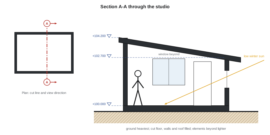
A section is a vertical cut through a building, viewed horizontally, like slicing a loaf of bread and looking at the cut face. As with a plan, everything the cutting plane passes through is drawn as cut, with the heaviest lines and a fill: the ground, the foundations, the floors, walls and roof. Everything seen beyond the cut, such as the far walls of the room, doors and windows in those walls, furniture and the outline of the building behind, is drawn with lighter lines. Sections are orthographic, so heights and depths are true at scale.
A section shows things no plan can: ceiling heights, the thickness of floors and roofs, how the building meets the ground, where light enters from above, how a stair rises, how one floor overlooks another, and how the structure carries loads down to the foundations. Architects use sections constantly while designing, because many of the most important spatial ideas, such as a double-height room, a mezzanine or a roof that lifts toward the view, can only be seen in section.
Where to cut
The position of the cut is a decision, and a good section is cut where it shows the most. Cut through the most important spaces, through stairs and changes of level, through windows and skylights, and across the shorter dimension of a building, where the structure usually spans. A section that passes between rooms, through a blank wall or along a corridor wall shows almost nothing. Many projects need at least two sections, one in each direction. The cut does not have to be straight: a jogged section steps sideways in plan to pass through two important places, as long as the plan marker shows the jog clearly.
The section is located on the plans by a section marker: a line drawn across the plan, usually heavy and dashed or with solid ends, with a symbol at each end showing the section's number and the sheet on which it is drawn, and an arrow or flag showing which way you are looking. On a single studio sheet you can simply label the cut line A–A and the drawing Section A–A.
The ground line and poché
Every section begins with the ground. Draw the ground line where the cut passes through the earth as the heaviest line in the drawing, and fill or hatch the earth below it to a short depth, enough to read as solid ground. A building section that floats on a thin line looks weightless and is hard to read. Where the building has a basement or foundations, the cut through them is part of the section too. On a sloping site like the bank at Kestrel Point, the ground line tells most of the story: where the building sits on the slope, how far it is above the river and what happens to the spring floodwater.
Poché is the old French word for the dark fill used to show cut material. In a section the poché of walls, floors and roof shows how thick the building's shell is and where the solid parts are. At small scales, all cut material can be solid black or a single dark tone. At larger scales, each material gets its own hatch: diagonal lines for masonry, a stipple and triangles for concrete, a wavy or cross-hatch pattern for insulation, end grain or parallel lines for wood. A legend on the sheet explains the hatches. Keep hatches lighter in weight than the outline of the cut, or the drawing will look muddy.
Levels and heights
Sections carry levels: the height of each floor, ceiling, roof and the ground, measured from a datum. In metric practice levels are given in metres to three decimal places, often relative to a project datum such as 100.000 at the main floor, so that a floor 2.7 m above is +102.700. Level markers are drawn as small triangles or circles with a line extending across the drawing at that height.
Floor-to-floor height and floor-to-ceiling height are not the same. Floor-to-floor is the distance from the top of one floor to the top of the next and includes the floor structure and services. Floor-to-ceiling is the clear height of the room. In a typical house the difference may be 300 to 400 millimetres (12 to 16 inches); in an office building with ducts above the ceiling it may be over a metre (3 feet). Section drawings are where these numbers are decided and checked.
# Stair geometry for a section: how many risers, how deep, and does it fit?
floor_to_floor = 3000
max_riser = 180
min_tread = 280
n = -(-floor_to_floor // max_riser)        # round up: number of risers
riser = floor_to_floor / n
tread = 280
run = (n - 1) * tread                       # one fewer tread than risers
rule = 2 * riser + tread                    # Blondel-type comfort rule
print(f"risers: {int(n)} at {riser:.0f} mm")
print(f"treads: {int(n) - 1} at {tread} mm, total run {run:.0f} mm")
print(f"2R + T = {rule:.0f} mm (comfortable range about 600 to 650 mm)")
print("tread meets minimum" if tread >= min_tread else "tread too short")risers: 17 at 176 mm treads: 16 at 280 mm, total run 4480 mm 2R + T = 633 mm (comfortable range about 600 to 650 mm) tread meets minimum
A stair drawn in section shows every riser and tread and the headroom above it. The script divides the floor-to-floor height into equal risers no taller than the code maximum, adds treads, and checks the old comfort rule, credited to the French architect François Blondel in 1675, that twice the riser plus the tread should fall in a narrow range. The run it prints is the length the stair needs in plan; the section must also show at least 2050 millimetres (6 feet 8 inches) of headroom over every tread, a common code minimum that you should check against the code in force.
Kinds of section
- Building section: the whole building cut through, at 1:100 or 1:50 (1/8 or 1/4 in = 1 ft), showing spaces, levels and the structure.
- Wall section: a slice through one wall from foundation to roof at 1:20 (3/4 or 1 in = 1 ft), showing every layer of the construction.
- Detail section: a small part at 1:5 or 1:10 (1-1/2 or 3 in = 1 ft), such as where a window meets a wall.
- Site section: a long section through the building and its surroundings, showing how it relates to the ground, trees, neighbouring buildings, roads or water.
- Section perspective: a section with the space beyond drawn in perspective, combining measured information with a sense of being inside.
- Sectional model: a physical or digital model cut open to show the interior.
The section perspective is one of the most powerful drawings in architecture. You draw the cut face as an ordinary orthographic section, then construct the room behind it in one-point perspective with the vanishing point at eye height in the middle of the room. You will learn the perspective method in lesson 6; keep it in mind as a way to make sections that both inform and persuade.
People, light and life in section
Put people in your sections, at the correct scale and doing what the building is for: sitting on the bench, climbing the stair, looking out of the window. A human figure is the quickest way for a reader to judge height. Draw them simply and lightly. Show light too: rays of sun entering through a window or skylight at the angle for a particular season and time, as you calculated in ARCH-100. In a section of the boathouse, a low winter ray reaching the back wall under the overhang and a high summer ray stopped by it says more about the design than a paragraph of explanation.
Sections are also where you show the building's relationship to the outdoors. Extend the ground line well beyond the building, draw the trees in the background in light line, and show the river at its normal and flood levels. A site section through the bank at Kestrel Point that shows the path, the boathouse floor above the flood line and the water beyond makes the design's main argument visible at once.
Precedent: sections that explain buildings
Some buildings are best understood in section. Le Corbusier's Unité d'Habitation in Marseille, completed in 1952, is a slab of flats in which each two-storey apartment interlocks with its neighbour around an interior street every third floor; the plan cannot explain this, but the section does at a glance. Louis Kahn's Kimbell Art Museum, opened in 1972, is a row of long concrete vaults split at their crown by a narrow slot; the section shows how daylight enters the slot, bounces off a curved metal reflector and washes down the inside of the vault. Closer to the studio, Étienne Gaboury's Precious Blood Church in Winnipeg, from 1968, rises in a spiral of shingled roof planes toward a central skylight, a form whose meaning you understand only when you draw it in section.
Worked problem
Drawing the boathouse floor above the flood line
The bank at the boathouse site drops 1.2 m (4 ft) over 6 m (20 ft) toward the river. The spring flood reaches 0.45 m (18 in) above the riverside path. Joon-ho wants the boathouse floor 0.15 m (6 in) above the flood level, with the path at level 100.000. What level is the floor, and how does it appear in section?
Show solution
- Flood level: 100.000 + 0.450 = 100.450.
- Floor level: 100.450 + 0.150 = 100.600.
- In section, draw the sloping ground line heavy, the flood line as a dashed line labelled with its level, and the floor slab cut and filled at the floor level, standing on short piers that pass through the flood zone.
- Add a level marker at the floor and a figure standing on it to show the height above the path.
Answer: The floor sits at 100.600. In section the relationship between floor, flood and ground can be read at once, which is why the section is the drawing that proves this design works.
Exercise 3: two sections
This exercise takes about five hours.
- Using your measured plan from lesson 2, mark two section lines on it, one in each direction, placed to show the most.
- Draw both sections at 1:50 (1/4 in = 1 ft): ground heavy with a short soil hatch, cut walls, floor and roof filled, elevations of walls beyond in lighter lines, a level marker at every floor and ceiling, and a figure for scale.
- Add sun rays for noon in December and in June, using the latitude of the place.
- Deliverable: the plan with section markers and the two sections, with a short note on what each section reveals that the plan does not.
Self-critique checklist
- Did I cut through the most important spaces, openings and changes of level?
- Is the ground line the heaviest line, with enough poché to read as solid?
- Do the plan markers point the right way and match the section titles?
- Are heights and levels marked and consistent with the plan?
- Is there a person at the correct scale?
Common mistakes
MistakeCutting the section through a blank wall or between rooms.
InsteadCut through the most important spaces, stairs, windows and level changes.
MistakeDrawing a thin ground line so the building floats.
InsteadMake the ground the heaviest line and hatch the earth below it.
MistakeSection markers pointing one way and the section drawn looking the other.
InsteadCheck the arrows on the plan match the view in the section.
MistakeLeaving out what is seen beyond the cut.
InsteadDraw far walls, openings and furniture beyond in lighter lines so the space reads.
Summary and key terms
- A section is a vertical cut through a building viewed horizontally, with sizes true at scale.
- Cut material is heaviest and filled; elements beyond are lighter; the ground is the heaviest line of all.
- Section markers on the plan show where each section is cut and which way it looks.
- Sections show heights, levels, structure, stairs, light and the building's relationship to the ground.
- Building, wall, detail and site sections, and section perspectives, each serve a different purpose.
- Section
- A vertical cut through a building, drawn as seen horizontally.
- Section marker
- A symbol on a plan showing the cut line, viewing direction and where the section is drawn.
- Level
- The height of a floor, roof or other element above a datum.
- Floor-to-floor height
- The distance from the top of one floor to the top of the next.
- Section perspective
- A section drawing with the space beyond the cut drawn in perspective.
Practice problems
Work each problem on paper first, then reveal the answer to check.
Which line should be heaviest in a building section?
Show answer
The ground line, along with cut floors, walls and roof.
What is a jogged section?
Show answer
A section whose cut line steps sideways in plan to pass through two important places.
A floor-to-floor height of 3000 mm (10 ft) is divided into risers no taller than 180 mm (7 in). How many risers are needed?
Show answer
17 (3000 ÷ 180 = 16.7, rounded up).
Why put people in sections?
Show answer
They give scale and show how the building is used.
What does a site section show that a building section might not?
Show answer
The building's relationship to the ground, landscape, neighbours and features such as water.
Lesson quiz · 5 questions
Score 60% or more to complete this lesson.
Create a free account to save your progress, take quizzes and earn a certificate.