
AERO-350 · Lesson 2 of 12 · 27 min
Electrical power systems
Electricity is the nervous system of a modern aircraft. It powers the avionics, the displays, the lights and the radios, and on newer designs it has taken over work once done by hydraulics and engine bleed air. On the Tern Block 2 it does far more: the propellers themselves are driven by electric motors, so the electrical system carries hundreds of kilowatts of propulsive power as well as the few kilowatts that run the rest of the aircraft. This lesson covers how aircraft electrical systems are organised, how engineers size them with an electrical load analysis, how they are protected, and what changes when the voltage rises from 28 V to the 800 V of the Tern's propulsion bus.
Sources, buses and architectures
Small and medium aircraft have traditionally used 28 V direct current. Each engine drives a starter-generator, a machine that turns the engine to start it and then generates power once the engine is running, and a battery supports engine starts and emergencies. Larger aircraft use 115 V alternating current, either at a constant 400 Hz from a generator with a constant-speed drive or, in newer designs, at a variable frequency between about 360 and 800 Hz from a generator driven directly by the engine. Some recent airliners add 270 V or ±270 V direct current for large electric loads such as cabin compressors.
Power is distributed through buses: conductors that collect power from sources and feed groups of loads through circuit breakers or solid-state power controllers. The architecture arranges buses so that the most important loads can always be fed. A typical scheme has main buses fed by the generators, essential buses that can be fed from either main bus or from the battery, and an emergency or hot battery bus connected directly to the battery for the few loads that must work in any situation. Bus tie contactors can connect the left and right sides if one generator fails, and automatic load shedding drops non-essential loads such as galley ovens or cabin entertainment when generating capacity is lost.
The Swift 900 study uses a conventional architecture: two 28 V starter-generators rated at 400 A each, one on each engine, a main lithium-ion battery, a standby battery for the emergency bus and a static inverter for the few loads that need alternating current. If both generators fail, the batteries must run the essential loads long enough to descend and land. Many standards, including the rules for business jets, express this as a duration, commonly 30 minutes for essential loads after loss of all normal generation, though the actual requirement depends on the aircraft's certification basis and its operating rules.
The Tern's two-voltage system
The Tern Block 2 has two electrical worlds. The high-voltage propulsion system runs at about 800 V direct current: the turboshaft-driven generator feeds a rectifier, the two battery strings feed through contactors, and the power distribution unit supplies the two 450 kW propeller motor inverters. The aircraft systems run from a conventional 28 V bus, fed by two 4 kW DC-DC converters that step the high voltage down, plus a dedicated 28 V emergency battery that is electrically separate from the propulsion batteries. The separation is deliberate: a fault in the high-voltage system must not be able to take the avionics, the flight controls or the displays with it.
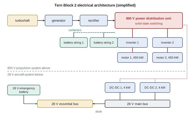
Why 800 V? Power is voltage times current, so for the 900 kW that both motors can draw at take-off, 800 V needs about 1100 A while 270 V would need more than 3300 A. Cable mass and resistive losses fall roughly with the current, so higher voltage saves weight. The price is insulation: high voltage at altitude is much harder to contain than at sea level, and the protection, inspection and maintenance training must be designed for it.
The electrical load analysis
The electrical load analysis, or ELA, is the basic sizing document for any aircraft electrical system and a required part of the certification data. It lists every load, its power, and how much of each flight phase it runs. Summing by phase gives the demand on the sources, which must be within their continuous rating with margin; summing the essential loads gives the battery size for emergencies. The ELA is revised every time a load is added, which on a long programme means many times, and it is one of the documents a new systems engineer is most likely to be handed on the first day.
Arjun's ELA for the Tern's 28 V bus groups the loads into eight lines. Each has a nameplate power and a duty factor for each of four phases: ground operation, take-off and climb, cruise and the emergency case in which both converters have failed and the 28 V emergency battery must carry the aircraft to a landing.
# Electrical load analysis for the Tern Block 2 28 V aircraft bus, the emergency battery size,
# and the efficiency chain from the turboshaft to the propeller shafts. Loads are illustrative.
loads = {  # name: (watts, fraction of time on in each phase: ground, take-off/climb, cruise, emergency)
    'avionics and displays':        (900, (1, 1, 1, 1)),
    'flight control actuators':     (650, (0.2, 0.6, 0.3, 0.5)),
    'propulsion controllers (28 V)': (420, (1, 1, 1, 1)),
    'battery cooling pumps':        (380, (0.5, 1, 0.7, 1)),
    'windshield heat':              (1500, (0, 0.5, 0.5, 0)),
    'lighting':                     (350, (1, 1, 0.4, 0.3)),
    'cabin fans and heater control': (600, (1, 0.8, 0.8, 0)),
    'fuel pumps (turboshaft)':      (300, (1, 1, 1, 1)),
}
phases = ('ground', 'take-off/climb', 'cruise', 'emergency')
cap = 2 * 4000.0   # two 28 V DC-DC converters from the high-voltage bus, 4 kW each
for i, ph in enumerate(phases):
    tot = sum(w * f[i] for w, f in loads.values())
    note = ''
    if ph != 'emergency':
        note = f"  {100*tot/cap:4.0f} % of both converters, {100*tot/(cap/2):4.0f} % of one"
    print(f"{ph:15s} {tot:6.0f} W{note}")

# Emergency battery: essential loads for 30 minutes after loss of both converters
P_em = sum(w * f[3] for w, f in loads.values())
t_em, V, dod, ageing = 0.5, 25.0, 0.8, 0.8      # hours, average volts, usable depth, end-of-life capacity
Ah = P_em * t_em / V / dod / ageing
print(f"\nemergency load {P_em:.0f} W for 30 min -> battery about {Ah:.0f} Ah at 28 V nominal")

# High-voltage chain efficiency, turboshaft shaft to propeller shaft
chain = {'generator': 0.96, 'rectifier and power distribution unit': 0.985,
         'cables': 0.99, 'motor inverter': 0.98, 'motor': 0.955}
eff = 1.0
for k, e in chain.items():
    eff *= e
    print(f"after {k:38s} {eff:.3f}")
P_shaft = 571.0
print(f"turboshaft must deliver {P_shaft/eff:.0f} kW for {P_shaft:.0f} kW at the propellers; "
f"heat to remove {P_shaft/eff - P_shaft:.0f} kW")ground 2890 W 36 % of both converters, 72 % of one take-off/climb 3970 W 50 % of both converters, 99 % of one cruise 3451 W 43 % of both converters, 86 % of one emergency 2430 W emergency load 2430 W for 30 min -> battery about 76 Ah at 28 V nominal after generator 0.960 after rectifier and power distribution unit 0.946 after cables 0.936 after motor inverter 0.917 after motor 0.876 turboshaft must deliver 652 kW for 571 kW at the propellers; heat to remove 81 kW
The demand peaks in take-off and climb at about 3970 W, half the capacity of both converters. With both converters working the margin is generous, but the design rule is that the aircraft must be safe after any single failure, and with one converter failed the take-off load is 99 percent of the survivor's rating. That is not acceptable as a continuous condition, so the design adds automatic load shedding: if one converter fails, the windshield heat and part of the cabin loads drop off, bringing the demand back to about 70 percent of one converter. Arjun records the shedding logic in the ELA and in the system requirements so that the test team knows to verify it.
In the emergency case the essential loads total about 2.4 kW. For 30 minutes at an average battery voltage of 25 V, allowing 80 percent usable depth of discharge and 80 percent of rated capacity at the end of the battery's life, the battery needs about 76 Ah. That is a heavy battery for a small aircraft, and Arjun's next task is to see which emergency loads can be reduced. The battery cooling pumps are in the list because the propulsion batteries must be kept within their temperature limits even when they are not being used, and the team decides to let the propulsion system power its own cooling through the distribution unit whenever the high-voltage system is available.
| Bus or source | Tern Block 2 | Swift 900 study |
|---|---|---|
| Main generation | Turboshaft generator to 800 V DC; two 4 kW DC-DC converters to 28 V | Two 28 V DC starter-generators, 400 A each |
| Storage | Two 800 V lithium-ion strings, 75 kWh each; 28 V emergency battery | Main lithium-ion battery and standby battery |
| Distribution | Power distribution unit with solid-state switching | Main, essential and emergency buses with tie contactors |
| Largest loads | Two 450 kW propeller motors | Windshield heat, pumps, avionics, cabin systems |
Converters, motors and efficiency
Every conversion stage loses a little energy as heat, and on a hybrid aircraft those small losses add up to a large heat load. The program follows the chain from the turboshaft's shaft to the propellers' shafts: generator, rectifier and distribution unit, cables, motor inverter, motor. With efficiencies between 95.5 and 99 percent each, the chain delivers 87.6 percent of the shaft power. For the 571 kW the propellers need at cruise, the turboshaft must provide 652 kW, the same figure Dr. Nakamura's propulsion group found in their analysis, and 81 kW of heat must be carried away by the cooling system. That is a larger heat load than the entire cabin and avionics cooling of many business jets, and it shapes the Tern's nacelle design.
Power electronics are now built mainly from silicon carbide transistors, which switch faster and run hotter than silicon, saving mass and cooling. Fast switching brings its own problems: high rates of voltage change stress motor insulation and generate electromagnetic interference that must be filtered so it does not reach the radios and navigation receivers.
Protection and wiring
Wires must be protected so that a fault cannot overheat them. Thermal circuit breakers have served for decades; solid-state power controllers now do the same job electronically, with programmable trip curves and the ability to report their status. Arc fault circuit breakers detect the erratic current of an electrical arc, which may be too small to trip an ordinary breaker but hot enough to start a fire in a wire bundle. The 1998 loss of a wide-body airliner off Nova Scotia, traced to arcing in wiring above the cockpit and flammable insulation blankets, led to major changes in wiring inspection and material flammability rules on both sides of the border.
Wiring itself is a system. The industry approach known as electrical wiring interconnection systems, or EWIS, treats the wires, connectors, clamps and routing as equipment that needs design, safety analysis and maintenance like any other. Redundant channels must be routed apart so that a single chafe, fire or bird strike cannot cut both. On the Tern, the two battery strings' harnesses run down opposite sides of the fuselage for exactly that reason, which supports the independence claimed in Lesson 1's fault tree.
High voltage at altitude
Air insulates less well as pressure falls. Paschen's law describes how the breakdown voltage of a gas gap depends on the product of pressure and gap distance, and for typical small gaps the breakdown voltage at the pressures found at cruise altitude is much lower than at sea level. Below full breakdown, partial discharge can occur: small discharges in voids within insulation or at sharp edges, which slowly erode the insulation until it fails. Voltages that are routine on the ground can therefore be dangerous in an unpressurized nacelle at 6000 m.
The Tern's high-voltage equipment is designed and tested for this. Connectors have long creepage paths and are sealed; cables use insulation systems qualified for partial discharge; and the equipment is tested in an altitude chamber at the lowest pressure it will see with margin. Marcus Webb's structures group has also had to learn something new: the battery boxes are pressure-tight enclosures with venting paths designed so that thermal runaway gases, if they occur, are carried overboard rather than into the cabin. Containment of battery thermal runaway is one of the special conditions Transport Canada has applied to the Tern.
Worked problem
Current and cable losses
The Tern's motors draw 900 kW at take-off. Compare the current at 800 V and at 270 V, and the resistive loss in a cable run of resistance 0.010 Ω.
Show solution
- At 800 V: \(I = 900\,000/800 = 1125\) A; loss \(= I^2 R = 1125^2 \times 0.010 = 12.7\) kW.
- At 270 V: \(I = 3333\) A; loss \(= 111\) kW with the same cable, so a much heavier cable would be needed.
Answer: 1125 A and 12.7 kW at 800 V against 3333 A and 111 kW at 270 V; this is the case for high voltage.
Worked problem
Battery capacity
An emergency bus draws 1.6 kW for 30 minutes from a 24 V average battery. With 80 percent usable depth of discharge and 80 percent end-of-life capacity, what rating is needed?
Show solution
- Energy \(= 1600 \times 0.5 = 800\) Wh; capacity \(= 800/24 = 33\) Ah.
- Rated \(= 33/(0.8 \times 0.8) = 52\) Ah.
Answer: About 52 Ah.
Worked problem
Heat from conversion
A motor inverter of 98 percent efficiency carries 450 kW. How much heat must its cooling remove?
Show solution
- Input \(= 450/0.98 = 459\) kW; heat \(= 459 - 450 = 9.2\) kW.
Answer: About 9 kW from each inverter, roughly the output of several electric home heaters.
Common mistakes
MistakeSizing a source to the normal load only.
InsteadThe load after any single failure, with shedding, must stay within the remaining sources' ratings.
MistakeIgnoring end-of-life battery capacity.
InsteadBatteries lose capacity with age and cold; the emergency duration must be met at the end of life.
MistakeTreating high voltage at altitude like high voltage on the ground.
InsteadInsulation breakdown and partial discharge occur at much lower voltages at low pressure.
MistakeRouting redundant wires in the same bundle.
InsteadA single chafe or fire would cut both; redundant channels need separate routes.
Summary and key terms
- Aircraft electrical systems use 28 V DC, 115 V AC or higher-voltage DC, with buses arranged so essential loads can be fed after failures.
- The electrical load analysis sizes sources and batteries by flight phase and after failures, with load shedding where needed.
- The Tern's 800 V propulsion system keeps cable currents and losses low but needs insulation designed for partial discharge at altitude, and its conversion chain delivers about 88 percent of the turboshaft's power to the propellers.
- Circuit protection, arc fault detection and wiring routing complete the safety picture.
- Starter-generator
- A machine that starts the engine and then generates electrical power.
- Essential bus
- A bus feeding loads needed for safe flight and landing, able to be supplied from several sources.
- Electrical load analysis
- The document that lists every electrical load by phase and checks sources and batteries.
- Load shedding
- Automatic disconnection of non-essential loads when generating capacity is lost.
- Solid-state power controller
- An electronic switch that replaces a circuit breaker and relay, with programmable protection.
- Partial discharge
- A small electrical discharge in insulation that erodes it over time, more likely at low pressure.
Practice problems
Work each problem on paper first, then reveal the answer to check.
In the program, add a 500 W de-icing controller that runs all of take-off and climb. What fraction of one converter is the climb load?
Show answer
About 112 percent, so more shedding or a larger converter is needed.
Why is the Tern's 28 V emergency battery separate from the propulsion batteries?
Show answer
So a high-voltage fault cannot remove the avionics, flight controls and displays.
What current does a 400 A, 28 V starter-generator correspond to in kilowatts?
Show answer
About 11.2 kW.
Name the law that describes gas breakdown voltage against pressure and gap.
Show answer
Paschen's law.
In the program, raise the motor efficiency to 0.97. What turboshaft power is needed?
Show answer
About 642 kW.
What does an arc fault circuit breaker detect that a thermal breaker may miss?
Show answer
The erratic current of an arc too small to trip a thermal breaker.
Lesson quiz · 5 questions
Score 60% or more to complete this lesson.
Create a free account to save your progress, take quizzes and earn a certificate.