
TRD-103 · Lesson 8 of 12 · 21 min
Plumbing and fire protection drawings
This is Maya's lesson. Plumbing drawings show the systems that bring clean water into the building, carry waste and storm water out, and keep the drains vented so they flow properly. Fire protection drawings show the sprinkler and standpipe systems that control fires. Both use the floor plans as a background and add their own symbols, line types, schedules and diagrams. Reading them well is the difference between an apprentice who waits to be told where every pipe goes and one who can rough in a bathroom from the drawings.
On Kingsway Tower the plumbing sheets are numbered P-001 to P-602 and drawn by the mechanical engineer, Delmar Engineering. The fire protection sheets, FP-101 to FP-112, show the design intent; the sprinkler contractor then prepares detailed sprinkler shop drawings and hydraulic calculations, which is common practice in the United States.
The plumbing legend
Every plumbing set starts with a legend, because plumbing has many systems that would otherwise look the same on a plan. Each system gets a line type or a label, and the common ones are fairly standard:
| System | Typical line or label | Notes |
|---|---|---|
| Sanitary drainage (soil and waste) | Solid heavy line, labeled S or W | Flows by gravity; sloped |
| Vent | Dashed line, labeled V | Carries air, lets drains flow and protects trap seals |
| Domestic cold water | Line with one short dash pattern, labeled CW or DCW | Under pressure |
| Domestic hot water | Line labeled HW or DHW | Under pressure |
| Hot water recirculation | Line labeled HWR or DHWR | Keeps hot water close to fixtures |
| Storm drainage | Line labeled ST or RD (rain drain) | Roof drains and area drains |
| Natural gas | Line labeled G | Pressure noted on drawings |
The legend also shows fitting and equipment symbols: cleanouts, floor drains, valves of each type, backflow preventers, water hammer arrestors, trap primers, hose bibbs, water heaters and pumps. Learn the ones on your project before you start reading the plans; looking them up later breaks your concentration every time.
Plumbing plans
Plumbing plans show the piping on each floor in plan. Because pipes run at different heights, a single floor often has more than one plumbing plan or a combined plan with careful labels:
- Below-grade or underground plans show the building drain and the storm drain under the lowest slab, with pipe sizes, slopes and invert elevations. On Kingsway Tower these are on the P2 plan.
- Typical floor plans show the fixtures in each unit, the branch drains and vents in the walls and floor, and the water piping usually run in the ceiling space of the floor below or in the walls.
- Enlarged plans show crowded areas such as bathroom groups, the mechanical room and the water service entrance at a larger scale.
- Roof plans show roof drains, vent terminations through the roof and any rooftop equipment connections.
Each pipe on the plan is labeled with its size and, for drainage, its slope. A label such as 100 S @ 1% or 4" S @ 1/8"/ft tells you the size, the system and the slope. Fixtures are tagged, for example WC-1 for a water closet of type 1 or LAV-2 for a lavatory of type 2, and the tags link to the plumbing fixture schedule.
Pipe sizes are given in nominal inches, such as 4" for a building drain or 3/4" for a water line. The nominal size is a name, not an exact diameter, as TRD-102 explained.
Slopes and invert elevations
Drains flow by gravity, so they have to slope. The plumbing code adopted in Ohio sets minimum slopes for drainage piping, commonly 1/4 in per foot for small drains and 1/8 in per foot for larger building drains. The plumbing drawings show the slope for each run, and the invert elevations at key points such as the building wall, cleanouts and the connection to the city sewer.
TRD-102 showed how to calculate the fall of a drain from its length and slope. On the drawings, the inverts let you check your work: the invert at the upstream end minus the fall along the run must equal the invert at the downstream end. If the drawings give inverts at both ends, the slope is fixed by the designer, and your job is to install the pipe so it matches.
Worked problem
Inverts along the building drain
The P2 plan shows the building drain starting at a cleanout at invert 76.80 ft and running 60 ft at 1/8 in per foot to the building wall, then 22 ft at 1/4 in per foot to the property line connection. What are the inverts at the wall and at the property line?
Show solution
- Fall to the wall: 60 x 1/8 = 7.5 in = 0.625 ft. Invert at the wall: 76.80 - 0.625 = 76.175 ft, about 76.18.
- Fall to the property line: 22 x 1/4 = 5.5 in = 0.458 ft. Invert at the property line: 76.175 - 0.458 = 75.717 ft, about 75.72.
- Compare with the civil drawings: the site plan shows the sewer connection invert at 75.60 ft, which is lower, so the drain can reach it.
Answer: Wall about 76.18 ft, property line about 75.72 ft. Checking against the civil drawings is how coordination problems are found before the trench is dug.
Riser diagrams and isometrics
A riser diagram shows the vertical stacks of a multistorey building: the soil and waste stacks, vent stacks, water risers and storm leaders, with each floor drawn as a horizontal line. It is usually not to scale, because its job is to show what connects to what, the pipe sizes and where they change, the cleanouts, the offsets and the vent connections. On a twelve-story building with dozens of stacks, the riser diagrams are the clearest way to understand the system.
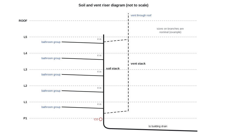
Many plumbing sets also show isometrics of typical bathroom groups or of the water service and meter assembly. Lesson 2 explained how to read them. If the drawings do not include an isometric for a complicated area, sketching your own from the plan and riser diagram, as Luis taught Maya, is the best way to check that you understand it before you cut any pipe.
Schedules and details
Plumbing schedules list the fixtures and equipment by tag. The fixture schedule gives each fixture type's manufacturer and model, or the basis of design, its mounting height, the sizes of its drain, vent, cold and hot water connections and any accessories, such as an accessible lever handle or a specific flush valve. Equipment schedules cover water heaters, pumps, backflow preventers, expansion tanks and sump pumps, with capacities and electrical data that the electrician needs too.
Plumbing details show standard installations: a floor drain with a trap primer connection and clamping ring for the waterproofing membrane, a cleanout at the base of a stack, a pipe hanger and its spacing, a water hammer arrestor, the water meter and backflow assembly, and the firestopping of pipes through rated walls and slabs. Many details are marked typical and apply throughout the building.
Fire protection drawings
Fire protection drawings show the automatic sprinkler system and, in a tall building like Kingsway Tower, the standpipe system that firefighters connect hoses to. Sprinkler systems in the United States are designed to NFPA 13, the sprinkler standard referenced by the building code, and the drawings show:
- The fire service entrance, with the backflow preventer, and the fire pump if one is needed.
- Risers and standpipes, usually in the stairwells, with hose valves at each floor.
- Floor control assemblies at each floor, with a control valve, flow switch and test and drain connection, so that each floor can be shut off and monitored separately.
- Mains and branch lines feeding the sprinkler heads, with pipe sizes.
- Sprinkler heads, shown as small circles or symbols by type: upright, pendent, sidewall, concealed, and the temperature rating where it matters.
- The fire department connection on the outside of the building, where the fire department pumps water into the system.
Sprinkler drawings change more than most during design, because the exact head layout depends on the final ceilings, bulkheads, lights and diffusers. The sprinkler contractor's shop drawings, coordinated with the reflected ceiling plans, are what actually gets built, and they go through review by the engineer and sometimes by the authority having jurisdiction before installation.
For other trades, the sprinkler drawings are a key coordination tool. Sprinkler mains are large, sprinkler heads must be kept clear of obstructions by set distances, and the standard limits what can be hung from sprinkler pipe. Maya has learned to check the sprinkler shop drawings before running her water lines through a corridor ceiling, because the sprinkler main has priority there by agreement among the trades.
Inverts in code
This program walks down a drain from one invert, applying the slope of each segment, and checks the result against the invert required at the downstream end, the same calculation as the worked example.
start_invert = 76.8          # ft
segments = [('to wall', 60, 0.010416666666666666), ('to property', 22, 0.020833333333333332)]   # (name, length, slope as a fraction)
required_end = 75.6

inv = start_invert
for name, length, slope in segments:
    fall = length * slope
    inv -= fall
    print(f"{name:14s} length {length:6.1f}  fall {fall:6.3f}  invert {inv:8.3f}")

margin = inv - required_end
print(f"end invert {inv:.3f} vs connection {required_end:.3f}: margin {margin:.3f} ft")
print("Drain can reach the connection" if margin >= 0 else "Drain too low: coordinate with the civil design")to wall length 60.0 fall 0.625 invert 76.175 to property length 22.0 fall 0.458 invert 75.717 end invert 75.717 vs connection 75.600: margin 0.117 ft Drain can reach the connection
A slope of 1/8 in per foot is 1/96 as a fraction, because a foot is 96 eighths; 1/4 in per foot is 1/48. Working in feet keeps the arithmetic simple.
Reading a bathroom group from the drawings
Putting the plumbing sheets together for one bathroom shows how they complement each other. For a typical bathroom in unit 405, Maya uses five sources:
- The enlarged architectural plan gives the exact positions of the toilet, tub and vanity, dimensioned from walls or grid lines, and the wall types.
- The interior elevations give the heights of the vanity, tub spout, shower valve and accessories.
- The plumbing plan shows the branch drain and vent routes, pipe sizes and slopes, and the water supply routes.
- The riser diagram shows how the bathroom group connects to the stack and the vent stack, and the stack size at that floor.
- The fixture schedule gives each fixture's rough-in requirements: drain and supply sizes and the manufacturer's rough-in dimensions, such as the distance from the finished wall to the center of the toilet outlet.
If any one of these disagrees with the others, she raises it before she starts. Fixture rough-in dimensions are a common trap: a toilet model with a different outlet distance from the one the architect drew can push the toilet into the door swing or leave a gap behind the tank. The fixture schedule and the manufacturer's data sheet are the authority for the fixture; the architect's plan is the authority for where it sits in the room.
Common mistakes
MistakeConfusing vent lines with drain lines because both are drawn as plain lines.
InsteadRead the legend: vents are usually dashed and labeled V.
MistakeInstalling a drain to the slope on the plan without checking the inverts.
InsteadCalculate the fall and check that the inverts at each end match the drawings.
MistakeTreating the riser diagram as a scaled drawing.
InsteadRiser diagrams are usually not to scale; use them for connections and sizes, and use plans and sections for locations.
MistakeRunning pipes through a corridor ceiling without checking the sprinkler shop drawings.
InsteadCoordinate with the sprinkler layout; sprinkler mains and head clearances often take priority.
MistakeIgnoring fixture tags.
InsteadEach tag links to the fixture schedule, which gives connection sizes and mounting heights.
Summary and key terms
- Plumbing legends define line types and symbols for each system: sanitary, vent, water, storm and gas.
- Plumbing plans show piping by floor, with sizes, slopes and fixture tags; underground plans show inverts.
- Invert elevations and slopes must agree: upstream invert minus fall equals downstream invert.
- Riser diagrams show stacks floor by floor and are usually not to scale.
- Fixture and equipment schedules give models, connection sizes and mounting heights.
- Fire protection drawings show sprinkler and standpipe systems; contractor shop drawings show the final layout.
- Sanitary drainage
- Piping that carries waste water from fixtures by gravity.
- Vent
- Piping that admits air to the drainage system so it flows freely and trap seals are protected.
- Riser diagram
- A diagram showing vertical stacks and their connections floor by floor.
- Fixture schedule
- A table of plumbing fixtures by tag with models and connection sizes.
- Cleanout
- An access fitting for clearing a drain.
- Trap primer
- A device that adds water to a floor drain trap so its seal does not dry out.
- Standpipe
- A vertical pipe with hose valves at each floor for firefighting.
- Fire department connection
- An outside connection where the fire department pumps water into the fire protection system.
- Floor control assembly
- A valve and switch assembly that controls and monitors the sprinklers on one floor.
Practice problems
Work each problem on paper first, then reveal the answer to check.
A 40 ft drain at 1/4 in per foot starts at invert 98.50 ft. What is the downstream invert?
Show answer
Fall 10 in = 0.833 ft, so 98.50 - 0.833 = 97.67 ft.
What does 3" W @ 1/4"/ft mean on a plan?
Show answer
A 3 in waste pipe sloped at 1/4 in per foot.
On which drawing do you see every floor's connection to a soil stack?
Show answer
The riser diagram.
What links a fixture tag such as WC-2 to its model and connections?
Show answer
The plumbing fixture schedule.
Who usually prepares the detailed sprinkler layout?
Show answer
The sprinkler contractor, in shop drawings based on the engineer's design.
Why are floor control assemblies used on each floor?
Show answer
So each floor's sprinklers can be shut off, tested and monitored separately.
Lesson quiz · 5 questions
Score 60% or more to complete this lesson.
Create a free account to save your progress, take quizzes and earn a certificate.