
TRD-103 · Lesson 2 of 12 · 22 min
Orthographic and isometric views
A building is three-dimensional, but a sheet of paper is flat. Every construction drawing solves that problem the same way: it shows the object from carefully chosen directions, one view at a time, and leaves it to the reader to put the views back together in their head. That skill, called visualization, is the core of blueprint reading. It feels awkward at first and becomes automatic with practice.
Maya's first real test comes in her second week, when Luis hands her the drawing of a concrete housekeeping pad for a domestic hot water heater in the mechanical room of Kingsway Tower. The drawing shows three rectangles and some dashed lines. Luis asks her what the pad looks like. This lesson gives her, and you, the tools to answer.
Orthographic projection
An orthographic view shows an object as if you were looking at it from very far away, straight on, so that all your lines of sight are parallel and square to the view. The word comes from Greek roots meaning straight and drawing. Because nothing is shown in perspective, distances measured on the view are true to scale in the two directions the view shows, which is exactly what a builder needs.
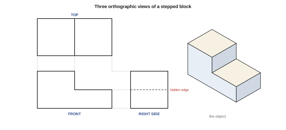
Imagine the object sitting inside a glass box. Look straight through each face of the box and trace what you see onto the glass. Then unfold the box flat. Each face of the glass box is one orthographic view. The three most common are:
- The front view, looking at the object from the front. On a building this is an elevation.
- The top view, looking straight down. On a building this is a plan.
- The side view, usually the right side, looking from the side. On a building this is another elevation.
Each view shows two of the object's three dimensions. The front view shows width and height; the top view shows width and depth; the side view shows depth and height. Any one view leaves out a dimension, which is why you need at least two views, and usually three, to describe an object completely.
How the views line up
Views are arranged in a fixed pattern so that you can project from one to another. North American drafting practice, reflected in the American technical drawing standards, generally uses what is called third-angle projection: the top view is placed directly above the front view, and the right side view directly to the right of the front view. Much of Europe and Asia uses first-angle projection, which swaps those positions. You may see a small symbol of a cone in the title block that tells you which system a drawing uses, especially on manufactured equipment drawings from overseas suppliers.
Because the views are aligned, every edge in one view lines up with the same edge in the next. A vertical line dropped from a corner in the top view meets the same corner in the front view. A horizontal line run across from the front view meets the same height in the side view. Drafters use these projection lines to draw the views, and readers use them to match features between views.
Building drawings take the same idea and spread it over many sheets. Plans are top views, elevations are front and side views, and sections, which lesson 6 covers, are views of an imaginary cut. The views are rarely on the same sheet, so instead of projection lines you use grid lines, dimensions and reference marks to match them up.
Visible, hidden and center lines
Each view shows every edge of the object that faces the viewer as a solid line. Edges that exist but are hidden behind something are shown as dashed lines, called hidden lines. A dashed line on a plan often means something above the cut, such as a bulkhead, a beam or an opening in the floor above, or something below, such as a footing under a slab. Lesson 4 lists all the line types; for now, remember that a dashed line means it is there but you cannot see it from this direction.
Round features such as holes, pipes and columns have a center line, a long line broken by short dashes, through their center. Center lines matter to the trades because pipes, sleeves and fixtures are laid out on their centers, as TRD-102 explained for offsets.
Reading a set of views
Here is the method Luis teaches Maya for the housekeeping pad, and it works for anything from a pipe support to a stair.
- Start with the view that shows the most characteristic shape, usually the one with the most detail.
- Find the overall size in each direction: width from the front or top view, depth from the top or side view, height from the front or side view.
- Pick one feature, such as a step, notch or hole, and find it in every view. Follow the projection or the dimensions from view to view.
- Explain each dashed line: what is hidden, and what is it hidden behind?
- Sketch the object in three dimensions, quickly, and check your sketch against every view.
Worked problem
The housekeeping pad
The front view of the pad is a rectangle 4 ft wide and 4 in high. The top view is a rectangle 4 ft by 3 ft with a dashed square 12 in on each side near one corner. The side view is a rectangle 3 ft wide and 4 in high with two dashed vertical lines 12 in apart that run the full height. What is the pad, and what is the dashed square?
Show solution
- Front view: 4 ft wide by 4 in high. Top view: 4 by 3 ft. So the pad is a slab 4 ft by 3 ft by 4 in.
- The square in the top view is dashed, so it is hidden from above. The side view shows dashed lines running the full 4 in height, so whatever it is goes right through the pad.
- Something hidden from above that goes through the full depth is a hole formed below the top surface or filled over. On this drawing a note identifies it as a 12 by 12 in blockout for a floor drain, formed through the pad and covered with a temporary lid.
Answer: A rectangular pad with a square blockout through it. If the blockout were open and visible from above, the top view would show it with solid lines.
The example shows how views and notes work together. Lines show shape, dimensions show size, and notes say what things are. Never guess the meaning of a line when a note or legend can tell you.
Pictorial drawings: isometric and oblique
Orthographic views are precise but hard to picture. Pictorial drawings show an object in a single three-dimensional view that is easier to understand at a glance. Two kinds are common in construction.
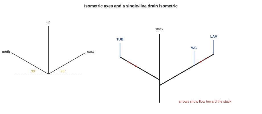
- An isometric drawing tilts the object so that its three main edges are drawn at equal angles to each other: one vertical, and two at 30° above the horizontal, to the left and right. Lines parallel to those axes are drawn to scale, so you can measure along them, but circles become ellipses and angles are distorted.
- An oblique drawing shows the front face true shape and size, with the depth drawn back at an angle, often 45°, and sometimes at half scale to look more natural. It is quick to sketch and often used for small details.
A perspective drawing, the kind an architect uses to sell a design to the owner, looks the most realistic because parallel lines converge toward vanishing points, but it cannot be measured, so tradespeople rarely work from one.
Isometrics in the piping trades
Pipe is the one place where isometric drawings are part of everyday work. Plumbers, pipefitters and steamfitters draw single-line isometrics, where each pipe is a single line, to show how a system runs in three dimensions. A plan shows where pipes run horizontally but hides vertical drops and rises; an elevation shows the rises but hides the horizontal directions. An isometric shows both at once.
Riser diagrams on plumbing sheets, which lesson 8 covers, are often drawn as isometrics or as simplified elevations. On industrial and large commercial jobs, fabrication isometrics show every pipe spool with its cut lengths, fittings, welds and elevations, and the shop builds directly from them.
The rule for drawing a pipe isometric is that each direction of the building gets an axis: north-south pipes run along one 30° line, east-west pipes along the other, and vertical pipes straight up and down. A pipe that runs at an angle in plan, such as a 45° offset, is drawn with a dashed or shaded triangle to show which plane it lies in. Luis has Maya sketch an isometric of every bathroom group before she roughs it in, with lengths and fitting types written on each segment.
Sam Torres uses the same skill for conduit. When a run of conduit has to climb a wall, cross a ceiling and drop into a panel, a quick isometric sketch with every bend marked tells him how many bends there are, so he can check that the total stays within the limit the National Electrical Code sets between pull points.
Projecting points in code
Isometric drawings follow simple geometry: each axis is drawn at a fixed angle, so any point in three dimensions has one position on the page. This program converts the corners of a pipe route into isometric page coordinates, the same calculation drawing software performs, and adds up the true length of pipe along the route.
import math

# route of a drain as (east, north, up) points; units: in
route = [(0, 0, 0), (96, 0, 0), (96, 60, 0), (96, 60, -36)]
c30 = math.cos(math.radians(30)); s30 = math.sin(math.radians(30))

def iso(e, n, u):
    """Isometric page position: east goes right-up, north goes left-up, up goes up."""
    return ((e - n) * c30, (e + n) * s30 + u)

length = 0
for i, p in enumerate(route):
    x, y = iso(*p)
    print(f"point {i}: page x = {x:8.1f}  y = {y:8.1f}")
    if i:
        q = route[i - 1]
        length += math.dist(p, q)
print(f"true pipe length along the route: {length:.0f} in")point 0: page x = 0.0 y = 0.0 point 1: page x = 83.1 y = 48.0 point 2: page x = 31.2 y = 78.0 point 3: page x = 31.2 y = 42.0 true pipe length along the route: 192 in
The page coordinates are what you would plot, while the true length comes from the three-dimensional points. On an isometric, lengths along the axes are true, but you cannot measure a diagonal on the page and expect the real length; you have to work it out, as the code does with math.dist.
From views to the site
Visualization is not just a classroom skill. When Maya stands in an empty concrete room with a plan in her hand, she has to picture where the walls will be, what will be above her in the ceiling, and where her pipes will come up through the floor. The best way to build that skill is to keep doing it: before starting any task, look at the plan and the section or elevation for the area, sketch what you expect to see, and then compare it with what is actually there. Over a few months, the flat drawings start to look three-dimensional on their own.
Common mistakes
MistakeReading a dashed line as a solid edge.
InsteadA dashed line is a hidden edge: it exists but is behind or below something in this view.
MistakeMeasuring a diagonal on an isometric drawing.
InsteadOnly lengths parallel to the three isometric axes are true. Work out other lengths from the dimensions.
MistakeTrying to understand an object from one view.
InsteadOne view shows only two dimensions. Use at least two views and match features between them.
MistakeAssuming every drawing uses third-angle projection.
InsteadCheck the projection symbol, especially on equipment drawings from overseas manufacturers.
MistakeGuessing what a feature is from its shape.
InsteadRead the notes and legend; lines show shape, but notes say what things are.
Summary and key terms
- Orthographic views show an object straight on from one direction, at true scale in two dimensions.
- Plans are top views, elevations are front and side views, and sections are views of an imaginary cut.
- North American practice generally places the top view above the front view and the right side view to its right.
- Hidden edges are dashed lines; center lines mark the centers of round features.
- Isometric drawings use one vertical and two 30° axes and are measurable only along those axes.
- Single-line pipe isometrics show horizontal and vertical runs together and are used throughout the piping trades.
- Orthographic projection
- A way of drawing an object in separate straight-on views, each showing two dimensions at true scale.
- Visualization
- Forming a three-dimensional picture in your mind from flat views.
- Third-angle projection
- The view arrangement common in North America, with the top view above the front view.
- Hidden line
- A dashed line showing an edge that cannot be seen in the view.
- Center line
- A long line broken with short dashes through the center of a round or symmetrical feature.
- Isometric drawing
- A pictorial drawing with one vertical axis and two axes at 30° to the horizontal.
- Oblique drawing
- A pictorial drawing with the front face true shape and the depth drawn back at an angle.
- Single-line isometric
- A piping drawing that shows each pipe as one line in isometric view.
Practice problems
Work each problem on paper first, then reveal the answer to check.
Which two dimensions does a plan view show?
Show answer
Width and depth (length and width of the floor), but not height.
In third-angle projection, where is the top view placed?
Show answer
Directly above the front view.
A footing appears as a dashed rectangle on a floor plan. Why?
Show answer
It is below the slab and hidden from above.
At what angles are the two horizontal axes drawn on an isometric?
Show answer
30° above the horizontal, one to each side.
Why do plumbers use isometric sketches?
Show answer
They show horizontal and vertical pipe runs together, with fittings and lengths, in one view.
Can you measure a sloped diagonal pipe directly from an isometric?
Show answer
No. Only lengths parallel to the isometric axes are true; diagonals must be calculated.
Lesson quiz · 5 questions
Score 60% or more to complete this lesson.
Create a free account to save your progress, take quizzes and earn a certificate.