
TRD-103 · Lesson 6 of 12 · 21 min
Elevations, sections and details
Plans tell you where things are horizontally. To know how high things are and how they are put together, you need the vertical views: elevations, sections and details. Together with the plans, they let you picture the whole building. This lesson works through each kind of vertical view on the Kingsway Tower drawings and shows how the heights on them become measurements on site.
Exterior elevations
An exterior elevation is a view of one face of the building, looking straight at it from outside. Kingsway Tower has four: north, south, east and west, each named for the direction the wall faces. Elevations show the building's appearance: cladding materials, windows and doors, balconies, the roof line and rooftop equipment screens. They also carry the vertical information that ties the floors together.
- Level markers show the elevation of each floor, the roof and other key heights. On Kingsway Tower they appear as a small target symbol or triangle on a horizontal line, with the level's name and elevation, such as Level 4 and its elevation.
- Grid lines are shown at the edges and at columns, so the elevation can be matched to the plans.
- Material notes or keynotes identify each cladding type, and the window tags link to the window schedule.
- Overall heights and important vertical dimensions, such as the height of a parapet or the sill height of a window.
For the trades, elevations answer questions like where the exterior wall penetrations go, where a hose bibb or an exterior light sits on the wall, and how the windows line up with the floors so that a pipe in an exterior wall avoids the window openings.
Levels and floor-to-floor heights
On Kingsway Tower the architectural drawings use a project datum: the top of the main floor slab, Level 1, is 100'-0", and every other level is measured from it. The typical floor-to-floor height, from the top of one slab to the top of the next, is 9'-6" on the residential floors, while the main floor is taller at 14'-6" for the lobby and retail space. So Level 2 is at 114'-6", Level 3 at 124'-0", and each typical floor 9'-6" above the one below. Underground, P1 is at 90'-0" and P2 at 80'-0".
Floor-to-floor height is not the same as ceiling height. Within each floor-to-floor height you have to fit the slab itself, any beams or drop panels, the space above the ceiling where pipes, ducts and conduit run, and the ceiling. That ceiling space, often called the plenum or interstitial space, is where most coordination problems between trades happen. Lesson 9 returns to it.
Building sections
A building section is a vertical cut through the whole building, as if it were sliced from roof to foundation and one half removed. The cut is shown on the plans with a cutting plane line and section bubbles. A building section shows how the floors stack up, the floor-to-floor heights, the structure, the shape of the roof, ramps in the parkade and how stairs and elevators connect the floors.
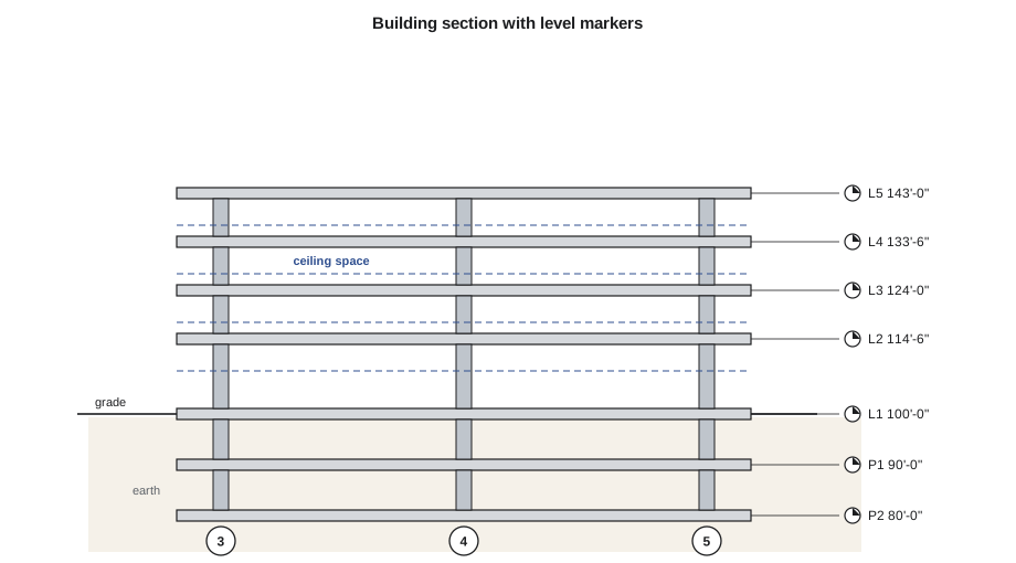
In a section, anything cut by the section plane is drawn heavy and hatched to show its material, just as walls are in a plan. Things beyond the cut, seen in the distance, are drawn with lighter lines. When you read a section, look first at its section mark on the plan to know where it is cut and which way you are looking.
Wall sections
A wall section is a larger-scale section, typically 3/4" = 1'-0", through one exterior wall from the foundation to the roof, or through a typical part of it. It shows every layer of the wall assembly in order: the cladding outside, an air gap or rainscreen cavity, weather barrier or air barrier, exterior insulation, sheathing, studs or concrete, any interior insulation, a vapor retarder where required, and the interior finish. It also shows how the wall meets each floor slab, the window heads and sills, and the roof parapet.
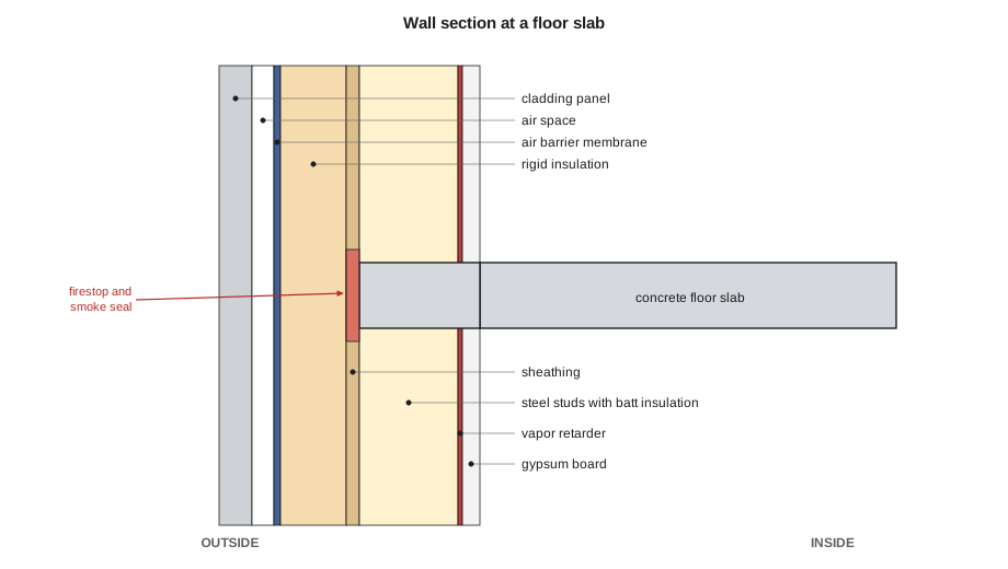
For the trades, the wall section answers practical questions. When Maya runs a hose bibb through the exterior wall, she cuts through every one of those layers, and each one has to be sealed again: the air barrier with a membrane boot or tape, the cladding with a flashing or sealant. When Sam mounts an exterior light, he needs to know whether there is solid backing behind the cladding or only insulation. The wall section is where you learn what you are cutting into before you cut.
Details
A detail is a large-scale drawing, typically 1-1/2" = 1'-0" or 3" = 1'-0", of one specific connection or condition: a window sill flashing, a roof drain, a pipe passing through a fire-rated wall, a toilet carrier anchored to a slab. Details are where the designer shows exactly how something is to be built, and they are referenced from plans, sections and keynotes with detail callouts.
Details are often typical: one detail drawn once applies wherever the same condition occurs. A typical firestop detail for a plastic pipe through a concrete slab might apply to hundreds of penetrations on Kingsway Tower. Some details are specific to one place and are labeled with the location. Many details for systems like firestopping or waterproofing come from the manufacturer, and the specification may require the exact tested system the detail shows.
When a detail and a smaller-scale plan or section disagree, the larger-scale drawing usually governs, because it was drawn to show that condition precisely. Many contracts say this outright. Even so, a disagreement is worth raising, because the smaller drawing may reflect a later change that the detail missed.
Interior elevations and mounting heights
An interior elevation looks at one wall of a room from inside. Kitchens, bathrooms, laundry rooms and the lobby have interior elevations on Kingsway Tower. They show cabinets, counters, tile, mirrors, grab bars, accessories, and the heights of fixtures, switches and receptacles. The interior elevation marker on the enlarged plan tells you which wall each elevation shows.
Heights on interior elevations and in mounting-height schedules are usually given above finished floor, AFF, to the centerline of the device or to its top or bottom edge. The general notes say which. The finished floor is the top of the final flooring, not the concrete, so if a bathroom gets 3/4 in of tile and mortar bed over the slab, a receptacle shown at 44" AFF is 44-3/4" above the concrete. Sam learned that the hard way on his first day of rough-in, when the foreman pointed out that his boxes would end up 3/4 in low after the tile.
Accessibility rules affect many mounting heights. Accessible units and public restrooms have rules for the heights of grab bars, controls, mirrors and fixtures, and the architect shows them on the elevations. Building something a few centimeters or an inch off in an accessible restroom can mean tearing it out at inspection, so these heights deserve extra care.
Worked problem
Heights from levels
Maya needs to set a sleeve in the formwork for the Level 6 slab. The plumbing section shows the sleeve's top flush with the top of the slab, and the drawings show the slab is 8 in thick. Level 6 is at 152'-6". What are the elevations of the top and bottom of the sleeve, and how high is the top above Level 5?
Show solution
- Top of sleeve = top of slab = 152'-6".
- Bottom of sleeve = 152'-6" - 8" = 151'-10".
- Level 5 = 152'-6" - 9'-6" = 143'-0".
- Height of top of sleeve above Level 5 = 152'-6" - 143'-0" = 9'-6".
Answer: Top 152'-6", bottom 151'-10", which is 8'-10" above Level 5. The top is a full floor-to-floor height, 9'-6", above Level 5.
Heights and clearances in code
This program builds a table of floor levels from the floor-to-floor heights, then checks how much space is left above a ceiling for services, which is what the trades fight over on every job.
levels = {"L1": 100.0}
heights = [("L2", 14.5)] + [(f"L{n}", 9.5) for n in range(3, 13)]
prev = 100.0
for name, h in heights:
    prev = round(prev + h, 3)
    levels[name] = prev
for name in ["L1", "L2", "L3", "L4", "L12"]:
    print(f"{name}: {levels[name]}")

# space above the corridor ceiling on a typical floor
floor_to_floor = 9.5
slab = 0.667
ceiling_height = 8.0        # finished floor to underside of ceiling
ceiling_thick = 0.052
space = floor_to_floor - slab - ceiling_height - ceiling_thick
print(f"space for services above the corridor ceiling: {space:.3f} ft")L1: 100.0 L2: 114.5 L3: 124.0 L4: 133.5 L12: 209.5 space for services above the corridor ceiling: 0.781 ft
About 9-1/2 in is all the room above the corridor ceiling on a typical floor for the sprinkler main, the domestic water lines, the ventilation duct and the cable trays. That is why the corridor ceiling space is the most coordinated piece of real estate in the building, and why the trades meet to plan it before anyone hangs anything.
Reading a section step by step
Sections hold a lot of information in a small space, and it helps to read them in a fixed order. Luis teaches Maya this routine, which works for building sections, wall sections and details alike:
- Find the section mark on the plan. Note where the cut is and which way the arrows point, so you know what you are looking at and from which side.
- Find the grid lines and level markers on the section and match them with the plan and elevations.
- Identify everything that is cut, drawn heavy and hatched, and what each material is from its hatching.
- Read the dimensions and elevations: slab thicknesses, ceiling heights, sill and head heights, and any heights of services.
- Read the notes and follow any detail callouts on the section to their larger-scale details.
- Picture where your own work fits, and check that the section agrees with your trade's drawings.
Following the same order every time means nothing is missed. It also builds the visualization skill from lesson 2: after a while, a section and its plan snap together into a three-dimensional picture without effort.
Elevations of shafts and stairs
Some vertical views exist mainly for the trades. Shaft sections and enlarged stair sections show the vertical spaces where pipes, ducts and cables rise through the building. On Kingsway Tower, the plumbing and mechanical shafts beside the elevator core are drawn in section at a large scale, showing each riser in its place, the access doors at each floor and the firestopping at each slab. Stair sections show landings, handrails and the heights of each flight, which matter to anyone running conduit or sprinkler pipe through a stairwell. Looking at these views before installing risers avoids the classic problem of two trades each assuming the same corner of a shaft is theirs.
Common mistakes
MistakeConfusing floor-to-floor height with ceiling height.
InsteadFloor-to-floor is top of slab to top of slab; the ceiling height is much less once the slab, structure and services are subtracted.
MistakeMeasuring mounting heights from the concrete.
InsteadAFF means above finished floor; add the thickness of the flooring when measuring from the slab.
MistakeReading a section without checking where it is cut.
InsteadFind the section mark on the plan first, and note which way the arrows point.
MistakeCutting through an exterior wall without reading the wall section.
InsteadKnow every layer you cut and how each one is to be sealed.
MistakeFollowing a small-scale drawing when a detail shows the condition.
InsteadThe larger-scale detail usually governs; raise any disagreement.
Summary and key terms
- Exterior elevations show the faces of the building, with level markers, grid lines and materials.
- Levels may use a project datum, such as 100'-0" for the main floor; floor-to-floor height runs top of slab to top of slab.
- Building sections show how the floors stack up; wall sections show every layer of the exterior wall.
- Details show specific connections at large scale and often apply wherever the condition is typical.
- Interior elevations give mounting heights above finished floor.
- The ceiling space is limited and shared, so heights matter to every trade.
- Elevation
- A view of a face of the building or a wall, looking straight at it.
- Level marker
- A symbol giving the name and elevation of a floor or other key height.
- Floor-to-floor height
- The vertical distance from the top of one floor slab to the top of the next.
- Building section
- A vertical cut through the whole building.
- Wall section
- A large-scale section through an exterior wall showing every layer.
- Detail
- A large-scale drawing of a specific connection or condition.
- Interior elevation
- A view of one wall of a room from inside.
- AFF
- Above finished floor; heights are measured from the top of the final flooring.
- Ceiling space (plenum)
- The space between a suspended ceiling and the structure above, where services run.
Practice problems
Work each problem on paper first, then reveal the answer to check.
Level 7 is at 171'-6" and floor-to-floor is 9'-6". What is Level 8?
Show answer
171'-6" + 9'-6" = 181'-0".
A receptacle is shown at 18" AFF in a room with 1/2 in vinyl over the slab. How high above the slab is it?
Show answer
18 + 1/2 = 18-1/2 in.
Which drawing shows the layers of an exterior wall?
Show answer
The wall section.
A plan and a 3" = 1'-0" detail disagree about a flashing. Which usually governs?
Show answer
The larger-scale detail, but the disagreement should still be reported.
What is the space above a suspended ceiling used for?
Show answer
Running services: pipes, ducts, sprinklers, cable trays and conduit.
Which direction does a north elevation face?
Show answer
North; it shows the north face of the building.
Lesson quiz · 5 questions
Score 60% or more to complete this lesson.
Create a free account to save your progress, take quizzes and earn a certificate.