
TRD-103 · Lesson 10 of 12 · 20 min
Electrical drawings
Now it is Sam Torres's turn. Electrical drawings show how power gets from the utility to every receptacle, light and motor in the building, and how the fire alarm, data, intercom and security systems are laid out. Electrical drawings rely more on symbols and diagrams than any other discipline, because wires are small and numerous; a plan that tried to draw every wire would be unreadable. Instead, symbols show the devices, short marks show the circuits, and diagrams and schedules show the rest.
Kingsway Tower's electrical sheets, E-001 to E-702, were drawn by Delmar Engineering's electrical group. The electrical work must meet the National Electrical Code, NFPA 70, as adopted in Ohio, and is inspected by the local electrical inspection authority. Each state, and sometimes each city, adopts a particular edition of the NEC with its own amendments.
The electrical legend
The first electrical sheet carries a long symbols legend. Symbols vary from firm to firm, but these are typical:
| Symbol | Meaning |
|---|---|
| Circle with two parallel lines | Duplex receptacle |
| Same with GFCI or GF beside it | Ground-fault circuit-interrupter receptacle |
| Same with a subscript such as C or WP | Receptacle above counter, weatherproof, or other special type |
| S | Single-pole switch |
| S3, S4 | Three-way and four-way switches (control from two or three places) |
| SD or S with D | Dimmer switch |
| Circle or rectangle with a letter tag | Light fixture (luminaire) of the type tagged |
| Square with J | Junction box |
| Long narrow rectangle, filled or hatched | Panelboard |
| Triangle | Data or telephone outlet |
| Circle with SD or S | Smoke alarm or smoke detector |
| Box with F | Fire alarm pull station |
Electrical drawings also use more abbreviations than most: EM for emergency, NL for night light, WP for weatherproof, TR for tamper-resistant, AFF for above finished floor, EC for electrical contractor, and many more. Sam keeps the legend sheet folded into his drawing binder for the first few weeks on any new project.
Power plans
A power plan shows receptacles, equipment connections, disconnect switches and junction boxes on each floor. Devices are placed where they will be installed, though their exact locations are often dimensioned only in critical places, such as above a kitchen counter or beside a bed in an accessible unit. Mounting heights come from the general notes, the interior elevations and any keynotes.
Each device is wired to a circuit, and circuits are shown in a kind of shorthand:
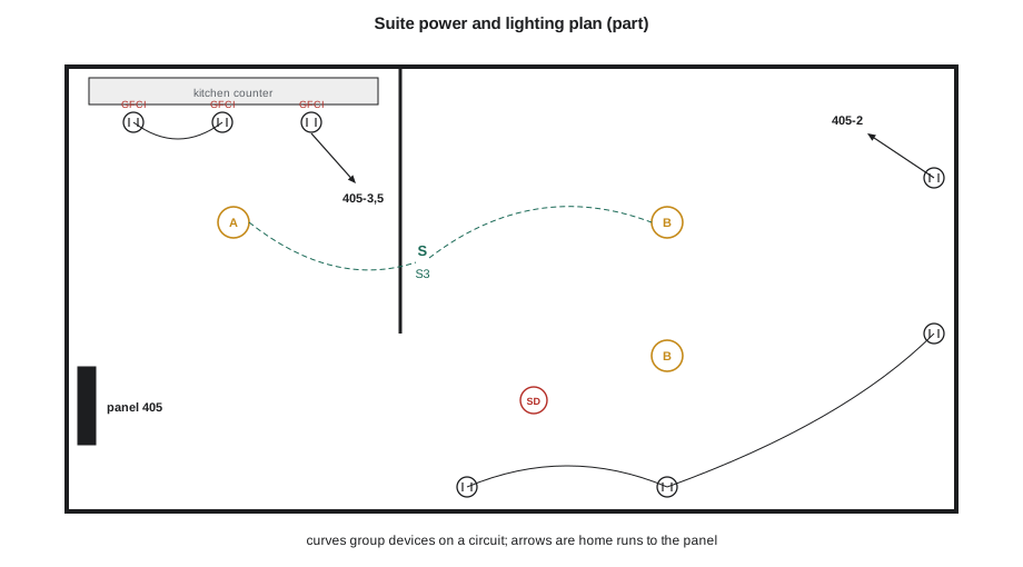
- Curved lines between devices show which devices share a circuit. They are not the wire route; the electrician chooses the route within the rules.
- Small slash marks on a circuit line can show the number of conductors, though many modern drawings leave this to the electrician.
- A home run is shown by an arrow pointing toward the panel, labeled with the panel name and circuit number, such as 4A-12. That means the circuit runs back to panel 4A, circuit 12. Several circuit numbers on one arrow, such as 4A-12,14, mean those circuits share the run back to the panel.
Worked problem
Tracing a circuit
On E-104, the receptacles above the kitchen counter in unit 405 are GFCI types connected by a curved line to a home run arrow marked 405-3,5. Where does Sam find the details of these circuits, and what does the label mean?
Show solution
- 405 is the panel name: on this project each suite has its own small panel named for the unit.
- 3 and 5 are two circuit numbers in that panel. Two circuits are used because the electrical code requires kitchen counter receptacles to be spread over more than one circuit.
- Sam opens the panel schedule for panel 405 on sheet E-601 and finds circuits 3 and 5: each is a 20 A breaker labeled Kitchen counter receptacles, with its load and wire size.
Answer: Panel 405, circuits 3 and 5; the panel schedule gives breaker size, load and description.
Lighting plans and luminaire schedules
Lighting is usually shown on separate plans from power, because the ceiling would otherwise be too crowded. Each light fixture, called a luminaire, is drawn as a symbol with a type tag, such as A, B or EX for an exit sign. The tag links to the luminaire schedule, which lists the manufacturer and model or basis of design, the lamp or LED source, wattage, voltage, mounting type and any special features such as emergency battery packs.
Switching is shown with lowercase letters: a switch marked Sa controls every fixture marked a in that room. Three-way switches, marked S3, let a light be controlled from two locations, such as both ends of a hallway. In common areas such as corridors and stairs, lighting may instead be controlled by occupancy sensors, timers or a lighting control panel, shown with their own symbols and described in a lighting control sequence.
Emergency lighting and exit signs are life-safety items required by the building code, and the drawings show which fixtures are on emergency power or have battery backup. In the United States exit signs are commonly the red or green lettered EXIT type, depending on local rules. Inspectors check these items closely.
Panel schedules
A panel schedule is a table for each panelboard, listing every circuit: its number, description, load in watts or volt-amperes, breaker size and number of poles, and which phase it is on. It also gives the panel's voltage, the number of phases, the main breaker or lugs, the bus rating and the feeder that supplies it. Odd-numbered circuits usually run down the left side of the panel and even-numbered circuits down the right, matching the physical layout of the breakers.
| Circuit | Description | Load (VA) | Breaker |
|---|---|---|---|
| 1 | Range | 8000 | 40 A 2-pole |
| 2 | Bedroom receptacles | 900 | 15 A |
| 3 | Kitchen counter receptacles | 1500 | 20 A |
| 4 | Bathroom receptacle | 1500 | 20 A |
| 5 | Kitchen counter receptacles | 1500 | 20 A |
| 6 | Lighting | 600 | 15 A |
| 7 | Refrigerator | 800 | 15 A |
| 8 | Heat pump HP-405 | 3200 | 25 A 2-pole |
The panel schedule is where Sam checks that his work matches the design: which breaker feeds which circuit, what size wire to use, and what the circuit serves. At the end of the job, a typed directory based on the schedule goes inside the panel door so that anyone working on the system can find the right breaker.
The single-line diagram
The single-line diagram, sometimes called a one-line, shows the whole power distribution system on one sheet as a simple diagram, with each feeder drawn as a single line no matter how many conductors it has. It starts at the utility service and shows the main switchboard, the meters, transformers, distribution panels, the riser to each floor, the suite panels, the emergency generator and transfer switch, and the large equipment such as elevators, fire pump and mechanical units. Each line is labeled with its feeder size and each device with its rating.
For apprentices, the single-line diagram is the map of the system. When a panel on the fifth floor needs to be shut off for work, the single-line shows which breaker in which upstream panel feeds it, which is the first step in the lockout procedure covered in TRD-101. Like riser diagrams, single-line diagrams are not to scale and do not show where equipment is located; the plans and the electrical room layouts do that.
Fire alarm and low-voltage systems
Fire alarm drawings show the devices that detect fires and alert occupants: smoke and heat detectors, manual pull stations, horns, strobes and speakers, and the connections to sprinkler flow and tamper switches, fire dampers, elevators and door holders. A riser diagram shows the fire alarm control panel, the annunciator at the main entrance where firefighters see which zone is in alarm, and the wiring to each floor.
Apartments in buildings like Kingsway Tower usually have their own smoke alarms, wired to the suite's power with battery backup and interconnected within the suite, as well as building fire alarm devices in the corridors. The building code and NFPA 72, the fire alarm code, set the rules, and the drawings show which devices belong to which system.
Low-voltage systems, sometimes on separate T or LV sheets, include data and telephone, cable television, intercom and door entry, security cameras, access control and the parking garage gas detection system. These are often installed by specialist contractors, but the electrician frequently installs the boxes, conduit sleeves and pathways for them, so Sam needs to read those sheets too.
Panel loads in code
This program adds up the loads on a suite panel by circuit and checks that no continuous load exceeds 80 percent of its breaker rating, a common design rule for continuous loads.
circuits = [  # (number, description, load VA, breaker amps, poles, continuous?)
    (1, "Range", 8000, 40, 2, False), (2, "Bedroom receptacles", 900, 15, 1, False),
    (3, "Kitchen counter", 1500, 20, 1, False), (4, "Bathroom receptacle", 1500, 20, 1, False),
    (5, "Kitchen counter", 1500, 20, 1, False), (6, "Lighting", 600, 15, 1, True),
    (7, "Refrigerator", 800, 15, 1, False), (8, "Heat pump HP-405", 3200, 25, 2, True),
]
total = 0
for num, desc, va, amps, poles, cont in circuits:
    volts = 240 if poles == 2 else 120
    current = va / volts
    flag = ""
    if cont and current > 0.8 * amps:
        flag = "  <-- over 80% for a continuous load"
    total += va
    print(f"{num:2d} {desc:22s} {va:5d} VA  {current:5.1f} A on {amps} A{flag}")
print(f"connected load {total} VA, about {total / 240:.0f} A at 240 V before any demand factor")1 Range 8000 VA 33.3 A on 40 A 2 Bedroom receptacles 900 VA 7.5 A on 15 A 3 Kitchen counter 1500 VA 12.5 A on 20 A 4 Bathroom receptacle 1500 VA 12.5 A on 20 A 5 Kitchen counter 1500 VA 12.5 A on 20 A 6 Lighting 600 VA 5.0 A on 15 A 7 Refrigerator 800 VA 6.7 A on 15 A 8 Heat pump HP-405 3200 VA 13.3 A on 25 A connected load 18000 VA, about 75 A at 240 V before any demand factor
The connected load is the total of everything that could be switched on, but the code allows demand factors because not everything runs at once. The engineer applies those rules to size the feeder; the panel schedule shows the result. The program is a check of the arithmetic, not a substitute for the code calculation.
Electrical rooms and working space
Electrical rooms on Kingsway Tower are drawn as enlarged plans showing the switchboard, transformers, panels, meter banks and the working space in front of each one. The National Electrical Code requires a clear working space in front of electrical equipment so that people can work on it safely, and the drawings show these spaces as dashed or hatched rectangles. Other trades must keep pipes, ducts and storage out of them, and the code also restricts piping that is not related to the electrical equipment from passing over it.
Maya has learned to check the electrical room plans before running any water line nearby, because a leak above a switchboard is a serious hazard.
Common mistakes
MistakeTreating curved circuit lines as the wire route.
InsteadThe curves show which devices share a circuit; the electrician chooses the actual route within the code rules.
MistakeReading 4A-12 as four amperes on circuit 12.
Instead4A is the panel name and 12 is the circuit number in that panel.
MistakePutting lighting and power on the same plan mentally.
InsteadLighting and power are often on separate sheets; check both for each room.
MistakeUsing the single-line diagram to locate equipment.
InsteadThe single-line shows connections and ratings, not locations; use the plans and room layouts.
MistakeSkipping the low-voltage sheets.
InsteadElectricians often provide boxes and pathways for low-voltage systems; read those sheets too.
Summary and key terms
- Electrical drawings use symbols for devices, curved lines for circuits and arrows for home runs.
- A home run label gives the panel name and circuit numbers, such as 4A-12,14.
- Lighting plans use fixture type tags and lowercase switching letters, with a luminaire schedule.
- Panel schedules list every circuit with its load, breaker, poles and phase.
- The single-line diagram shows the power distribution system from the service to every panel.
- Fire alarm and low-voltage systems have their own drawings, legends and riser diagrams.
- Home run
- The part of a circuit that runs back to the panel, shown by an arrow with the panel and circuit number.
- Panelboard
- An enclosure containing breakers that distribute power to branch circuits.
- Panel schedule
- A table of every circuit in a panel with its load and breaker.
- Luminaire
- A complete light fixture.
- Single-line diagram
- A diagram of the power system with each feeder shown as one line.
- Three-way switch
- A switch that, with another, controls a light from two places.
- GFCI
- Ground-fault circuit interrupter, a device that cuts power when current leaks to ground.
- Annunciator
- A panel showing which fire alarm zone or device is in alarm.
- Connected load
- The total load of everything connected to a panel or circuit.
Practice problems
Work each problem on paper first, then reveal the answer to check.
What does a home run arrow labeled 2B-7,9 mean?
Show answer
Circuits 7 and 9 in panel 2B share the run back to the panel.
Where would you find the wattage of light fixture type C?
Show answer
In the luminaire schedule.
A switch is marked Sb. What does it control?
Show answer
The fixtures marked b in that room.
A 1440 VA continuous load is on a 15 A, 120 V circuit. Is it within 80 %?
Show answer
1440 / 120 = 12 A, and 80 % of 15 A is 12 A, so it is exactly at the limit.
Which drawing shows which breaker feeds a fifth-floor panel?
Show answer
The single-line diagram.
Name two low-voltage systems an electrician might provide boxes and pathways for.
Show answer
Any two of data, telephone, intercom, security cameras, access control or cable television.
Lesson quiz · 5 questions
Score 60% or more to complete this lesson.
Create a free account to save your progress, take quizzes and earn a certificate.