
PWR-210 · Lesson 11 of 12 · 27 min
Basic electricity for the plant
▶ Video coming soon A video version of this lesson is on the way.
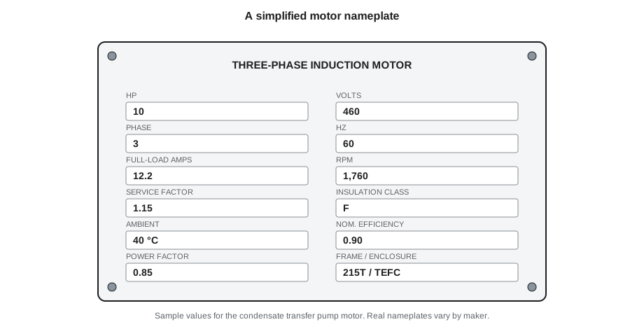
On Wednesday, November 4, 2026, Ruaridh Brasseur, the electrician who looks after Cantwell's motors and switchgear, came in to check the condensate transfer pump motor after the night shift logged it running warm. Tamar Ellingsen was assigned to help with the isolation and to watch. Before he opened anything, Ruaridh tapped the motor's nameplate. "Most of what you need to know about this machine is written right here," he said. "Read it to me, and tell me what each number means. Then we'll see whether the motor agrees with its plate."
This lesson covers the basic quantities of electricity, Ohm's law, electrical power and energy, series and parallel circuits, alternating current, single-phase and three-phase power, power factor, and how to read a motor nameplate. It gives a power engineer enough electrical understanding to read meters, log loads and talk sensibly with electricians. Electrical work itself is done by qualified, authorized people under the plant's electrical safety program, and PWR-240 goes further into motors, starters and generators.
Voltage, current and resistance
Electricity is the movement of electric charge, usually electrons moving through a conductor such as a copper wire. Three quantities describe a simple circuit:
- Voltage (V), measured in volts, is the electrical pressure that pushes charge around a circuit. It is like the pressure a pump develops in a water system.
- Current (I), measured in amperes or amps (A), is the rate at which charge flows. It is like the flow rate of water in a pipe.
- Resistance (R), measured in ohms (Ω), is how strongly a part of the circuit opposes the current. It is like the friction of a narrow or rough pipe.
The water comparison is useful up to a point. A pump that makes more pressure pushes more flow through the same pipe; a higher voltage pushes more current through the same resistance. A narrower pipe passes less flow at the same pressure; a higher resistance passes less current at the same voltage.
Ohm's law
For most conductors at a steady temperature, the current is directly proportional to the voltage and inversely proportional to the resistance. That is Ohm's law, and any one of the three quantities can be found from the other two.
Worked problem
Current in a panel heater
The anti-condensation heater in the switchgear cabinet runs on 120 V and has a resistance of 240 Ω. What current does it draw?
Show solution
- \[I = \frac{V}{R} = \frac{120}{240} = 0.5 \text{ A}\]
Answer: Half an amp. Small heaters like this keep moisture from condensing inside electrical cabinets in damp spaces such as boiler rooms and steam vaults.
Electrical power and energy
Electrical power, the rate at which a circuit converts electrical energy into heat, light or motion, is measured in watts, the same unit as mechanical power (lesson 3). For a direct current circuit, or a purely resistive alternating current circuit such as a heater, power is voltage times current. Combining that with Ohm's law gives two more useful forms.
The form P = I²R shows why current matters so much: double the current through a conductor and the heat it produces rises four times. Loose connections, undersized wires and overloaded motors all show up first as heat, which is why thermographic surveys of switchgear find faults before they fail.
Worked problem
An electric unit heater
An electric unit heater in the water treatment room is rated 4,500 W at 240 V. What current does it draw, and what is its resistance when hot?
Show solution
- Current:
- \[I = \frac{P}{V} = \frac{4{,}500}{240} = 18.75 \text{ A}\]
- Resistance:
- \[R = \frac{V}{I} = \frac{240}{18.75} = 12.8 \text{ Ω}\]
Answer: 18.75 A, with a hot resistance of 12.8 Ω. The anti-condensation heater, at 120 V and 0.5 A, uses 120 × 0.5 = 60 W, less than one seventieth as much.
Electrical energy is power multiplied by time. The utility bills it in kilowatt-hours (kWh): one kilowatt for one hour, equal to 3.6 MJ. A 7.5 kW motor running for 8,000 hours a year uses about 60,000 kWh. That conversion is the bridge between the electrical bill and the plant's energy balance in lesson 12.
Series and parallel circuits
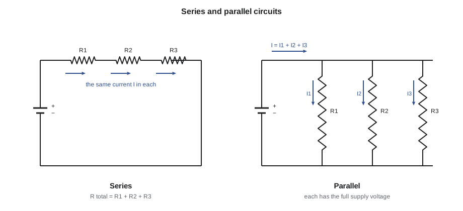
In a series circuit, components are connected end to end so the same current flows through each. The total resistance is the sum of the individual resistances, and the supply voltage is shared among them. If one component opens, the whole circuit stops, which is why safety interlocks such as the low-water cutoff and flame safeguard contacts are wired in series: any one of them opening shuts down the burner.
In a parallel circuit, components are connected across the same two points so each has the full supply voltage. The currents add, and the total resistance is less than the smallest individual resistance. Lights and outlets in a building are wired in parallel so that each can work on its own.
Lesson 8 used the same idea for heat: the layers of soot, steel and scale in a tube wall are resistances in series, and their resistances add.
Direct and alternating current
Direct current (DC) flows steadily in one direction, as from a battery. Plant control systems, uninterruptible power supplies, emergency lighting and some instruments use DC. Alternating current (AC), supplied by the utility, reverses direction many times a second. In North America, it completes 60 cycles each second: a frequency of 60 hertz (Hz). AC is used for power distribution because transformers can easily raise its voltage for transmission and lower it for use.
AC voltages and currents are stated as their effective, or root-mean-square, values, which produce the same heating as DC of that value. Common supply voltages in US plants are 120/240 V single-phase for small loads, and 208 V or 480 V three-phase for motors and large equipment, with motors nameplated at 460 V for a 480 V system.
Three-phase power and power factor
Most plant motors run on three-phase power: three separate AC voltages, each a third of a cycle out of step with the others. Three-phase power delivers a smoother flow of energy than single-phase, lets motors start and run without extra starting devices, and carries more power for the same amount of copper.
In an AC circuit with motors, transformers or other coils, the current does not rise and fall exactly in step with the voltage. Part of the current builds and collapses magnetic fields rather than doing work. The power factor (PF) is the fraction of the apparent power that does real work, between 0 and 1. A heater has a power factor of 1; a loaded induction motor typically has 0.8 to 0.9; a lightly loaded motor has much less.
Here V is the line-to-line voltage, I is the line current, and P is the real power in watts drawn from the supply. The product √3 × V × I alone is the apparent power, in volt-amperes (VA) or kVA, which sizes the cables and transformers. Utilities may charge large customers for a poor power factor, because the extra current loads their system without delivering energy.
Worked problem
Full-load current of a motor
The condensate transfer pump motor is rated 10 hp (7.46 kW) output at 460 V three-phase, with a power factor of 0.85 and an efficiency of 0.90 at full load. Estimate its full-load current.
Show solution
- Electrical input at full load:
- \[P_{\text{in}} = \frac{7{,}460}{0.90} \approx 8{,}289 \text{ W}\]
- Current:
- \[I = \frac{8{,}289}{\sqrt{3} \times 460 \times 0.85} \approx 12.24 \text{ A}\]
Answer: About 12.2 A, close to the full-load amps on the nameplate. The rated power of a motor is its mechanical output at the shaft; the electrical input is larger because of the motor's losses.
Reading a motor nameplate
A motor nameplate is the motor's specification in brief. Its most important entries are:
- Rated output in kW or hp: the mechanical power the motor can deliver continuously at its shaft.
- Voltage, phase and frequency: the supply it is built for. A motor may be built for more than one voltage, connected differently for each.
- Full-load amps (FLA): the current at rated output and voltage. It is the starting point for checking whether the motor is overloaded.
- Speed in rpm at full load. A four-pole induction motor on 60 Hz runs a little below 1,800 rpm, the difference being its slip.
- Service factor: a multiplier above 1.0 showing how much continuous overload the motor can tolerate under stated conditions, at the cost of higher temperature and shorter life. A service factor of 1.15 allows up to 1.15 times rated output.
- Insulation class and ambient temperature: the temperature limits of the winding insulation and the cooling air it was designed for.
- Efficiency and power factor, often at full load, and the frame size and enclosure type, such as totally enclosed fan cooled.
In the US, motors are built to NEMA standards, and federal energy efficiency rules set minimum efficiencies for many general-purpose motors.
Checking the motor against its plate
A clamp-on ammeter reads the current in one conductor without breaking the circuit, and many meters also read voltage and power factor. Measured current compared with nameplate FLA is the simplest check on a motor's load: well below FLA means the motor has power to spare; above FLA means it is overloaded, has a supply problem, or has a mechanical problem such as a failing bearing or a pump running far out on its curve. A measured current that differs noticeably between the three phases points to a voltage imbalance or a winding fault, which overheats a motor quickly.
Worked problem
What the motor is actually drawing
Ruaridh measured 11.2 A in each phase at 460 V, with a power factor of 0.84. What is the motor's electrical input, and roughly how loaded is it?
Show solution
- Input power:
- \[P = \sqrt{3} \times 460 \times 11.2 \times 0.84 \approx 7{,}500 \text{ W}\]
- Approximate output at an efficiency of 0.90:
- \[7{,}500 \times 0.90 \approx 6{,}750 \text{ W}\]
Answer: About 7.5 kW in and 6.75 kW out, or about nine tenths of the motor's rating, with the current below FLA and balanced across the phases. Electrically the motor was healthy. The warm running had another cause, which Ruaridh found a few minutes later: the cooling fan cover was packed with lint and dust from a nearby insulation job, so the motor could not shed its heat.
Electrical safety for operators
A power engineer's role with electrical equipment is to operate it safely, monitor it and report faults, not to repair it. Basic rules apply everywhere:
- Treat every conductor as live until it has been isolated, locked out and tested by a qualified person, as the lockout procedure from PWR-110 requires.
- Keep electrical room doors closed and access clear; never store materials in front of switchgear.
- Never defeat an interlock, overload relay or ground fault device, and never replace a fuse with a larger one.
- Report hot, buzzing or smelling equipment, tripped breakers that trip again, and any sign of water near electrical gear.
Arc flash, the explosive release of energy from a fault in switchgear, can cause severe burns at a distance. US workplaces follow NFPA 70E for workplace electrical safety, and only trained and authorized workers wearing the right protective equipment operate or work near exposed energized parts.
Back in service
With the fan cover cleaned and the motor restarted, Tamar logged its current every hour for the rest of the shift. It stayed steady and the frame cooled to its usual temperature. Ruaridh added the fan cover to the monthly motor inspection checklist and suggested a dust barrier the next time insulation work was done near running equipment. "The plate told us what the motor should do, the meter told us what it was doing, and the difference told us where to look," he said.
Meters an operator uses
Operators read electrical quantities every shift without opening any equipment. Switchgear and motor control centers carry panel meters for voltage, current and often power and power factor; variable frequency drives display motor current, speed and power on their keypads; and the utility's revenue meter records the plant's energy use in kWh and its peak demand in kW. Logging these alongside the mechanical readings ties the electrical side into the plant's records. A motor's current that creeps up week by week at the same duty is as useful a trend as a rising stack temperature: it may point to a bearing going, a pump wearing or a fan damper sticking. Portable instruments such as clamp ammeters and multimeters are rated for the voltage and the category of circuit they may be used on, and only people trained and authorized under the plant's electrical safety program use them on live circuits.
Common mistakes
MistakeConfusing the motor's rated output with its electrical input.
InsteadThe rating is shaft output; input is larger by the losses.
MistakeForgetting the power factor in three-phase power.
InsteadReal power is √3 × V × I × PF.
MistakeAssuming a warm motor is always electrically overloaded.
InsteadCheck current against FLA, phase balance and the cooling path.
MistakeReplacing a blown fuse with a larger one.
InsteadFind the cause; the fuse size protects the circuit.
MistakeRelying on a switch being off without testing.
InsteadIsolate, lock out and verify absence of voltage under the plant's procedure.
Summary and key terms
- Voltage pushes current through resistance; Ohm's law V = IR links them.
- Power P = VI = I²R = V²/R; energy is power times time, billed in kWh.
- Series circuits share current and add resistances; parallel circuits share voltage and add currents.
- AC in North America is 60 Hz; three-phase power is P = √3 × V × I × PF.
- A motor nameplate gives rated output, voltage, FLA, speed, service factor and insulation class.
- Compare measured current with FLA and check phase balance to judge a motor's load and health.
- Voltage
- The electrical pressure that drives current, measured in volts.
- Current
- The rate of flow of electric charge, measured in amperes.
- Resistance
- Opposition to current, measured in ohms.
- Ohm's law
- The relationship V = IR.
- Power factor
- The fraction of apparent power in an AC circuit that does real work.
- Three-phase
- A supply of three AC voltages a third of a cycle apart, used for motors.
- Full-load amps
- The current a motor draws at rated output and voltage.
- Service factor
- A nameplate multiplier showing the continuous overload a motor can tolerate.
Practice problems
Work each problem on paper first, then reveal the answer to check.
A 120 V lamp draws 0.5 A. What is its power?
Show answer
60 W.
What current flows through 20 Ω connected to 240 V?
Show answer
12 A.
Three 10 Ω resistors are in series. What is the total resistance?
Show answer
30 Ω.
A three-phase motor draws 20 A at 460 V with PF 0.85. What is its input power?
Show answer
About 13.5 kW.
How many kWh does a 15 kW fan use in 200 hours?
Show answer
3,000 kWh.
Lesson quiz · 5 questions
Score 60% or more to complete this lesson.
Create a free account to save your progress, take quizzes and earn a certificate.