
PWR-120 · Lesson 11 of 12 · 23 min
Plant auxiliaries: compressors, fans and pumps
▶ Video coming soon A video version of this lesson is on the way.
On Tuesday, November 3, 2026, a low pressure alarm on the instrument air system interrupted Tamar's morning round. The lead compressor was running flat out, but the header pressure was sagging and the standby compressor had just cut in. Lorne found the cause in ten minutes: the refrigerated dryer's automatic drain had stuck open, and compressed air was hissing straight to the floor drain. He isolated the drain, opened its manual bypass for a few seconds every half hour, and put in a work order. "The boilers get the attention," he said, "but the plant stops without its air, its fans and its pumps. Every one of these auxiliaries has a way of telling you it's in trouble, if you're listening."
This lesson covers the auxiliary equipment that keeps a boiler plant running: compressed air systems for instruments and service, the fans that move combustion air and flue gas, the pumps that move water around the plant, and the motors, drives, bearings and seals they share. It ends with the routine checks an operator makes on rounds.
Compressed air
Most boiler plants have two compressed air systems. Instrument air operates control valves, damper actuators, and pneumatic controls and instruments; it must be clean, dry and oil-free, because water or oil in an instrument line can freeze, corrode or jam a controller. Service air runs air tools and blowing and cleaning jobs and need not be as clean. Some plants make both from the same compressors and treat the instrument air further.
A typical system has:
- Compressors, often rotary screw compressors for steady duty or reciprocating (piston) compressors for smaller or intermittent loads, with an intake filter.
- An aftercooler, which cools the hot compressed air and condenses much of its water vapor.
- An air receiver, a pressure vessel that stores air, smooths pressure swings and lets condensed water settle out. It has a safety valve, a pressure gauge and an automatic drain, and it is a registered pressure vessel subject to inspection.
- A dryer: a refrigerated dryer chills the air to about 37 °F (typical) to condense more water, while a desiccant dryer passes it through a drying medium for a much lower dew point where lines could freeze.
- Filters and drains downstream, and pressure regulators at the points of use.
Compressors start and stop, or load and unload, on pressure switches or a controller. A lead-lag arrangement runs one compressor as lead and starts the second if the pressure falls further. A compressor that runs continuously when it normally cycles, or a standby compressor that keeps cutting in, means the system is using or losing more air than it should: a leak, an open drain, or a control valve or actuator bleeding air. Air leaks are expensive, because compressed air is one of the costliest forms of energy in a plant.
Air receivers are pressure vessels built to ASME Section VIII and are inspected under Ohio's pressure vessel rules where they are covered; the compressors themselves are not licensed in Ohio, though some states and cities do license compressor operators.
Worked problem
How fast is the air leaking?
With the dryer drain closed, Lorne shut off the compressors and timed the receiver. Pressure fell from 100 psig to 85 psig in 50 seconds. The receiver and piping hold about 70 cubic feet. Using the rule that free air lost ≈ volume × pressure drop ÷ atmospheric pressure, about how much free air per minute is the system losing when nothing is using air?
Show solution
- Free air lost:
- \[70 \times (100 - 85) \div 14.7 \approx 71.4 \text{ ft}^3\]
- Per minute:
- \[71.4 \div 50 \times 60 \approx 86 \text{ ft}^3\text{/min}\]
Answer: About 86 cubic feet of free air per minute even with every drain closed and no planned demand, which means steady leaks in the system on top of the failed drain. Lorne added a leak survey with an ultrasonic detector to the maintenance plan. The test is approximate: it ignores temperature changes, but it is a quick way to see whether leakage is small or large.
When instrument air fails completely, pneumatic valves move to their fail-safe positions: fuel valves close, feedwater valves often fail open so the boilers don't lose water, and dampers go to set positions. An operator should know the fail position of every major pneumatic valve in the plant, and the plant's procedure for loss of instrument air, before it happens.
Fans
Fans move air for combustion and gas out of the boiler. Forced draft (FD) fans push combustion air into the burner; induced draft (ID) fans, on boilers that have them, pull flue gas out through the boiler and push it up the stack. Ventilation fans supply the boiler room and exhaust heat. Cantwell's packaged boilers have their FD fans built into the burner housings, and the plant has two supply fans and two exhaust fans for the boiler room.
Most boiler fans are centrifugal fans, in which a wheel with blades flings air outward into a scroll casing. Axial fans, with propeller-like blades, are used where large volumes move against low pressure, as in many ventilation fans. Airflow is controlled by dampers, by inlet vanes, or increasingly by changing the fan's speed with a variable frequency drive (VFD), which saves a great deal of energy at part load because of the fan laws.
The affinity laws
Fans and centrifugal pumps follow the same simple rules when their speed changes, called the affinity laws or fan laws. For the same fan or pump and the same system:
- Flow changes in proportion to speed.
- Pressure (or head) changes with the square of the speed.
- Power changes with the cube of the speed.
The cube law is why VFDs save so much: running a fan or pump at 80 in 100 of its speed delivers 80 in 100 of the flow but needs only about half the power.
Worked problem
Energy saved by slowing a pump
Cantwell's hot water loop pump draws 60 hp at full speed. On a mild day the drive runs it at 70 in 100 of full speed. About what power does it draw, and what flow does it deliver if full speed gives 475 gpm?
Show solution
- Power:
- \[60 \times 0.70^3 = 60 \times 0.343 \approx 20.6 \text{ hp}\]
- Flow:
- \[475 \times 0.70 \approx 333 \text{ gpm}\]
Answer: About 20.6 hp for about 333 gpm, about a third of the full-speed power for 70 in 100 of the flow. In practice the savings are a little less because of drive and motor losses and the system's static head, but the principle holds.
Pumps around the plant
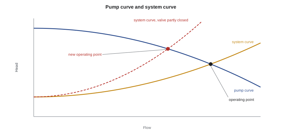
Besides the feedwater pumps (lesson 4), a boiler plant has condensate transfer pumps, hot water circulating pumps, chemical feed pumps, fuel oil pumps, sump pumps and often cooling water pumps. Most are centrifugal. A centrifugal pump has a pump curve, supplied by the manufacturer, showing the head it develops at each flow. It works where its curve crosses the system curve, which shows how much head the piping needs at each flow. Closing a valve steepens the system curve and moves the pump back along its curve to less flow and more head.
Pumps are often installed in parallel (two pumps feeding the same header, each carrying part of the flow, so either can run alone if the other fails) or in series (one feeding the next, adding their heads). Standby pumps are rotated on a schedule so each one gets regular run time and none sits idle for months and seizes.
A centrifugal pump's shaft passes through its casing, and the gap is sealed either with packing, rings of braided material compressed by a gland, or with a mechanical seal, two flat faces, one rotating and one fixed, pressed together. Packing is meant to drip slightly, a few drops a minute, to lubricate and cool itself; tightening it until it stops dripping burns the packing and scores the shaft. A mechanical seal should not leak visibly; a leaking seal needs replacement. Hot water and feed pumps often have seal flush or cooling lines that must be kept open.
Motors, drives, bearings and alignment
Most auxiliaries are driven by electric induction motors, coupled to the pump or fan through a flexible coupling. If the motor and the pump shafts are not lined up accurately, the coupling and the bearings wear quickly and the machine vibrates, so couplings are aligned after installation and whenever a motor or pump is replaced. Belt-driven fans need correct belt tension and pulley alignment.
Bearings support the shafts. Rolling element bearings (ball and roller) are greased or oil-lubricated on a schedule; too much grease can be as harmful as too little, because it makes the bearing run hot. Sleeve bearings run on an oil film from a ring or a pump. Operators check bearing temperatures by touch where it is safe, or with an infrared thermometer, and listen for changes in sound. A bearing that is hotter than its neighbors or that has started to growl or squeal is reported before it fails.
Vibration is the best early warning of trouble in rotating equipment. Many plants measure it on a schedule with a handheld meter or by a contractor's vibration analysis, and the trend over time matters more than any single reading. A rising trend may mean misalignment, imbalance, a worn bearing or cavitation.
| Symptom | Possible causes |
|---|---|
| Pump noisy, like gravel, flow low | Cavitation: low suction head, clogged strainer, hot suction water |
| Bearing running hot | Over- or under-lubrication, misalignment, worn bearing |
| Vibration rising over weeks | Misalignment, imbalance, wearing bearings, loose mounting |
| Packing leaking heavily | Packing worn or gland loose; adjust slightly, repack if needed |
| Motor tripping on overload | Pump running off its curve, mechanical binding, electrical fault |
| Compressor running continuously | Air leak, stuck drain, high demand, worn compressor |
Electrical safety around auxiliaries
Auxiliary equipment is where most plant operators work closest to electrical equipment: motor control centers, starters, VFDs and local disconnects. Operators start and stop equipment with the controls provided and lock out at the disconnect for maintenance (PWR-110 lesson 5), but they do not open starter or drive enclosures or work on live electrical parts unless they are qualified and authorized to. A VFD holds a dangerous charge in its capacitors for minutes after it is switched off, and the drive's label states the waiting time.
Rounds on auxiliaries
| Equipment | Check |
|---|---|
| Air compressors | Running hours and loading normal, discharge temperature, oil level, drains working |
| Air receiver and dryer | Pressure in range, safety valve sealed, dryer dew point indicator normal, drains cycling |
| Fans | Running smoothly, belts tracking, no unusual noise or vibration, dampers in expected position |
| Pumps | Suction and discharge pressures, packing drip or seal tight, bearing temperatures, noise |
| Motors | Current within nameplate, no hot smell, cooling fins clear |
| Standby equipment | Ready to start; rotated on schedule |
By the end of the day the dryer's drain valve had been replaced and the standby compressor was back on standby. Tamar added the leak-down test result to the log, and Grazyna asked for it to be repeated monthly so the plant could see whether the leak survey made a difference.
Starting and stopping a centrifugal pump
Starting a pump the wrong way can damage it in seconds, so plants follow a set routine. For a typical centrifugal pump:
- Check the pump is ready: lockouts removed, guards in place, bearings lubricated, seal flush or cooling water on.
- Open the suction valve fully. A pump must never run with its suction closed, because it would cavitate and overheat at once.
- Vent and prime the casing so it is full of water, not air.
- Start the pump with the discharge valve closed or only slightly open, as the procedure says, so the motor does not have to accelerate the full flow at once. Then open the discharge valve slowly.
- Check that discharge pressure rises to its normal value, that the motor current settles within nameplate, and that there is no unusual noise or vibration.
A centrifugal pump should not run for more than a short time against a closed discharge valve, because all the energy it takes in turns into heat in the water trapped in its casing. Feed pumps and other pumps that may run at low flow have a minimum flow recirculation line that returns a small flow to the tank to keep the pump cool.
To stop a pump, close the discharge valve slowly, stop the motor and then, if the pump is being taken out of service, close the suction valve and lock out. Closing the discharge first keeps the check valve from slamming and the piping from water hammer. When a standby pump takes over, the operator starts the standby, confirms it is carrying the load, and only then stops the running pump.
Common mistakes
MistakeTightening pump packing until it stops dripping.
InsteadLeave a small drip; dry packing burns and scores the shaft.
MistakeIgnoring a standby compressor that keeps cutting in.
InsteadIt means a leak, an open drain or extra demand; find it.
MistakeGreasing bearings until grease pours out.
InsteadFollow the schedule and quantity; over-greasing makes bearings run hot.
MistakeOpening a VFD enclosure right after stopping the drive.
InsteadCapacitors stay charged; only qualified people work inside, after the labeled wait.
MistakeLeaving a standby pump unrun for months.
InsteadRotate standby equipment on schedule.
Summary and key terms
- Instrument air must be clean and dry; compressors, aftercoolers, receivers, dryers and drains supply it.
- Pneumatic valves go to fail-safe positions on loss of air; know them before it happens.
- Fans move combustion air and flue gas; dampers, vanes or VFDs control the flow.
- Affinity laws: flow ∝ speed, pressure ∝ speed², power ∝ speed³.
- Centrifugal pumps run where their curve meets the system curve; packing drips, mechanical seals don't leak.
- Alignment, lubrication and vibration trends keep rotating equipment healthy.
- Instrument air
- Clean, dry compressed air for controls and actuators.
- Air receiver
- A pressure vessel that stores compressed air and separates water.
- Affinity laws
- Rules relating flow, pressure and power of fans and pumps to speed.
- Variable frequency drive
- An electronic drive that changes motor speed.
- Mechanical seal
- A shaft seal made of two flat faces pressed together.
- Fail-safe position
- The position a valve or damper goes to when its power or air is lost.
Practice problems
Work each problem on paper first, then reveal the answer to check.
Why must instrument air be dry?
Show answer
Water can freeze, corrode or jam controls and actuators.
A fan runs at 50 in 100 speed. What fraction of full power does it need, by the affinity laws?
Show answer
About one-eighth (0.5³ = 0.125).
How should pump packing be adjusted?
Show answer
To leave a slight drip, a few drops a minute.
What is the best early warning of rotating equipment trouble?
Show answer
A rising vibration trend.
What happens to fuel valves when instrument air fails?
Show answer
They close (fail-safe).
Lesson quiz · 5 questions
Score 60% or more to complete this lesson.
Create a free account to save your progress, take quizzes and earn a certificate.