
PHYS-381 · Lesson 6 of 12 · 22 min
Conductors, capacitance and boundary conditions
A conductor is a material in which some charges, electrons in a metal or ions in a solution, are free to move. Put a conductor in an electric field and its free charges move until the field inside it vanishes. That simple fact has far-reaching consequences: it fixes where charge sits on a conductor, makes every conductor an equipotential, explains electrostatic shielding, and defines capacitance. This lesson works out the properties of conductors from the boundary conditions of lesson 4, computes the capacitance of the standard geometries, and treats the energy and forces associated with charged conductors.
The basic properties of conductors
In electrostatic equilibrium nothing moves, so the force on every free charge inside a conductor must be zero. Therefore:
- \(\mathbf{E} = \mathbf{0}\) inside the conductor. If it were not, free charges would move. The induced charges arrange themselves to cancel any applied field inside, and they do so very quickly; in a good metal the relaxation time is far shorter than a nanosecond.
- \(\rho = 0\) inside. Gauss's law gives \(\rho = \varepsilon_0\nabla\cdot\mathbf{E} = 0\). Any net charge resides on the surface.
- The conductor is an equipotential. For any two points inside or on it, \(V(\mathbf{b}) - V(\mathbf{a}) = -\int\mathbf{E}\cdot d\mathbf{l} = 0\).
- Just outside, \(\mathbf{E}\) is perpendicular to the surface. A tangential component would push surface charges along the surface.
Combining the last property with the boundary condition of lesson 4, and using \(\mathbf{E} = \mathbf{0}\) on the inside, the field just outside a conductor is
where \(\hat{\mathbf{n}}\) is the outward normal and \(\partial V/\partial n\) the derivative along it. Note the factor: twice the field of an isolated sheet with the same \(\sigma\), because inside the conductor the field of the local surface charge is canceled by the field of all the other charges, which therefore add to it outside.
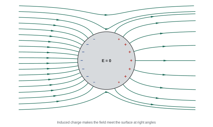
The figure shows a neutral conducting sphere placed in a uniform field. Electrons shift toward the left, leaving the right side positive. The induced surface charge turns out to be \(\sigma = 3\varepsilon_0 E_0\cos\theta\), as lesson 8 will derive, and the field lines bend so that they meet the surface at right angles. The total induced charge is zero, but its distribution changes the field everywhere nearby.
Cavities and shielding
Suppose a conductor has a hollow cavity with no charge inside it. Then the field in the cavity is zero. To see why, suppose a field line existed in the cavity. It would have to start and end on the cavity wall, so the line integral of \(\mathbf{E}\) along it would be nonzero, giving a potential difference between two points of the same conductor. That contradicts the conductor being an equipotential. So the cavity is completely shielded from external fields, however strong, which is the principle of the Faraday cage, demonstrated by Faraday in 1836 inside a large wire-mesh room. If instead a charge \(q\) is placed inside the cavity, an equal and opposite charge \(-q\) is induced on the cavity wall, and \(+q\) appears on the outer surface, distributed as if the cavity were not there. The outside world knows how much charge is inside but not where it is. Shielded cables, microwave oven doors and the metal body of a car struck by lightning all rely on these properties.
Charge on curved surfaces
Charge on a conductor is not spread uniformly; it concentrates where the surface curves most sharply. A simple model shows why. Two conducting spheres of radii \(R_1\) and \(R_2\), far apart but joined by a thin wire, must have the same potential, so \(Q_1/R_1 = Q_2/R_2\). The surface charge density \(\sigma = Q/4\pi R^2\) is then inversely proportional to the radius, and so is the surface field. A sharp point behaves like a very small sphere, so the field there can exceed the breakdown field of air, about 3 MV/m, and the air ionizes. This is the principle of the lightning rod, proposed by Benjamin Franklin in the 1750s, and of the corona discharge visible as a faint glow on high-voltage lines in damp weather.
Capacitance
Consider two conductors carrying charges \(+Q\) and \(-Q\). Because the field is proportional to the charge by superposition, so is the potential difference \(V\) between them. The ratio is the capacitance,
which depends only on the sizes, shapes and separation of the conductors and on the material between them. It is measured in farads, coulombs per volt, after Faraday. A farad is enormous; practical capacitors range from picofarads to millifarads, apart from supercapacitors that reach thousands of farads by using enormous internal surface areas. Three geometries can be solved with Gauss's law.
For parallel plates of area \(A\) and separation \(d\) with \(d\) much smaller than the plate size, the field between them is \(\sigma/\varepsilon_0 = Q/(\varepsilon_0 A)\) and \(V = Qd/(\varepsilon_0 A)\), so \(C = \varepsilon_0 A/d\). For concentric spheres of radii \(a < b\), \(V = \frac{Q}{4\pi\varepsilon_0}\big(\frac1a - \frac1b\big)\), so \(C = 4\pi\varepsilon_0\frac{ab}{b - a}\); letting \(b \to \infty\) gives the capacitance of an isolated sphere, \(4\pi\varepsilon_0 a\). For a coaxial cable with inner radius \(a\) and outer radius \(b\), the field is that of a line charge, \(V = \frac{\lambda}{2\pi\varepsilon_0}\ln(b/a)\), and the capacitance per unit length is \(2\pi\varepsilon_0/\ln(b/a)\). Filling the space with an insulator of dielectric constant \(\varepsilon_r\) multiplies each by \(\varepsilon_r\), as lesson 9 explains.
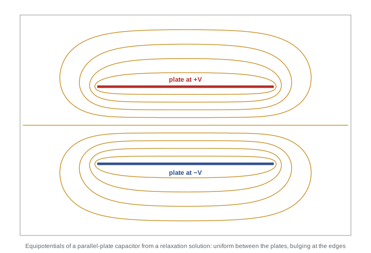
The formula \(\varepsilon_0 A/d\) ignores the fringing field at the edges, where the equipotentials bulge outward. The figure, computed by the relaxation method of lesson 7, shows the effect. Fringing adds a little charge on the edges and outer faces of the plates, so a real capacitor has slightly more capacitance than the ideal formula; for plates much wider than their spacing the correction is small, of order \(d/L\).
Computing capacitance, charge sharing and force
The program evaluates the three standard formulas for practical dimensions: 10 cm square plates 1 mm apart, a coaxial cable with polyethylene insulation of the size used for 50-ohm laboratory cable, the whole Earth as an isolated sphere, and a pair of concentric spheres. For the cable it also computes the inductance per unit length, \(\frac{\mu_0}{2\pi}\ln(b/a)\), which lesson 10 will justify, and from these the characteristic impedance and wave speed. Then it shares 50 nC between two joined spheres of radii 1 cm and 10 cm, and finally it computes the force between capacitor plates in two ways.
import math
eps0 = 8.8541878188e-12
# 1. Capacitance of three standard geometries
A, d = 0.01, 1e-3
print(f"parallel plates 10 cm x 10 cm, 1 mm gap: C = {eps0*A/d*1e12:.2f} pF")
a, b, er = 0.45e-3, 1.47e-3, 2.25           # coaxial cable: inner and outer radii, polyethylene
Cl = 2*math.pi*eps0*er/math.log(b/a)
Ll = 4e-7*math.pi/(2*math.pi)*math.log(b/a)
print(f"coaxial cable: C = {Cl*1e12:.1f} pF/m, L = {Ll*1e9:.0f} nH/m, "
      f"impedance {math.sqrt(Ll/Cl):.1f} ohm, wave speed {1/math.sqrt(Ll*Cl)/2.998e8:.3f} c")
R_e = 6.371e6
print(f"isolated sphere the size of the Earth: C = {4*math.pi*eps0*R_e*1e6:.0f} uF")
r1, r2 = 0.10, 0.12
print(f"spherical capacitor 10 cm / 12 cm: C = {4*math.pi*eps0*r1*r2/(r2-r1)*1e12:.1f} pF")

# 2. Charge on two connected conducting spheres: same potential, surface field ~ 1/radius
k = 1/(4*math.pi*eps0); Qt = 50e-9; R1, R2 = 0.01, 0.10
Q1 = Qt*R1/(R1 + R2); Q2 = Qt - Q1
print(f"spheres 1 cm and 10 cm joined: Q1 = {Q1*1e9:.2f} nC, Q2 = {Q2*1e9:.2f} nC, "
      f"V = {k*Q1/R1:.0f} V, surface fields {k*Q1/R1**2:.0f} and {k*Q2/R2**2:.0f} V/m")

# 3. Energy stored and the force on a plate, two ways
V0 = 100.0; C = eps0*A/d
U = 0.5*C*V0**2
F_field = 0.5*eps0*(V0/d)**2*A                       # pressure eps0 E^2/2 times area
Q = C*V0; dd = 1e-9
F_energy = (0.5*Q*Q*(d + dd)/(eps0*A) - 0.5*Q*Q*d/(eps0*A))/dd   # at fixed charge
print(f"plates at {V0:.0f} V: U = {U*1e9:.2f} nJ, force from pressure {F_field*1e6:.3f} uN, "
f"from -dU/dx at fixed Q {F_energy*1e6:.3f} uN")parallel plates 10 cm x 10 cm, 1 mm gap: C = 88.54 pF coaxial cable: C = 105.7 pF/m, L = 237 nH/m, impedance 47.3 ohm, wave speed 0.667 c isolated sphere the size of the Earth: C = 709 uF spherical capacitor 10 cm / 12 cm: C = 66.8 pF spheres 1 cm and 10 cm joined: Q1 = 4.55 nC, Q2 = 45.45 nC, V = 4085 V, surface fields 408525 and 40853 V/m plates at 100 V: U = 442.71 nJ, force from pressure 442.709 uN, from -dU/dx at fixed Q 442.709 uN
The parallel plates have 88.5 pF, a typical small capacitor. The coaxial cable has about 106 pF per meter and an impedance of 47 ohms, close to the 50-ohm standard; signals travel along it at two thirds of the speed of light, because the polyethylene slows them by \(1/\sqrt{\varepsilon_r}\). The entire Earth, treated as an isolated conducting sphere, has a capacitance of only 709 μF, which shows how large a farad is. The joined spheres share the charge in proportion to their radii, 4.55 nC on the small one and 45.45 nC on the large one, but the small sphere's surface field, 409 kV/m, is ten times larger. Finally, the energy stored at 100 V is 443 nJ, and the force on a plate is 443 μN computed either from the field pressure or from the change in energy with separation.
The characteristic impedance found for the cable deserves a word. A signal traveling along a coaxial cable is an electromagnetic wave confined between the conductors, and the ratio of the voltage to the current in that wave is \(\sqrt{L/C}\), set entirely by the geometry and the insulation. Matching the impedance of the cable to the instruments at each end prevents reflections, which is why laboratories standardize on 50-ohm cable and television antennas on 75-ohm cable. PHYS-382 derives these results from Maxwell's equations; here the static capacitance and inductance already determine them.
Energy and force
The energy stored in a capacitor is the work done moving charge from one plate to the other against the growing potential difference,
which agrees with \(\frac{\varepsilon_0}{2}\int E^2\,d\tau\) for the field between the plates. The surface of a conductor feels an outward pressure equal to the energy density just outside,
where the factor of one half arises because the surface charge feels the average of the fields just inside and just outside. For an isolated capacitor, with fixed charge, the force is \(F = -\partial W/\partial x\) at constant \(Q\), and the program confirms that this equals the pressure times the plate area. If the capacitor is instead connected to a battery at fixed voltage, the battery does work as the plates move, and the force is \(+\partial W/\partial x\) at constant \(V\); it is the same force, as it must be, because the plates do not know what is connected to them.
Worked problem
A coaxial cable
A coaxial cable has an inner conductor of radius 0.50 mm and an outer conductor of inner radius 2.0 mm, with air between them. Find its capacitance per meter and the maximum voltage it can hold if air breaks down at 3.0 MV/m.
Show solution
- \(C/l = 2\pi\varepsilon_0/\ln(4) = 5.563 \times 10^{-11}/1.386 = 40.1\) pF/m.
- The field is largest at the inner conductor: \(E(a) = V/(a\ln(b/a))\).
- Setting \(E(a) = 3.0 \times 10^6\) V/m: \(V = 3.0 \times 10^6 \times 5.0 \times 10^{-4} \times 1.386 = 2.08\) kV.
Answer: About 40 pF per meter, with breakdown at roughly 2.1 kV, starting at the inner conductor.
Common mistakes
MistakeThinking the field inside a conductor is zero because there is no charge there.
InsteadIt is zero because induced charges cancel any applied field; that is why there is no interior charge.
MistakeUsing \(\sigma/2\varepsilon_0\) just outside a conductor.
InsteadThe field just outside a conductor is \(\sigma/\varepsilon_0\).
MistakeAssuming charge spreads uniformly over any conductor.
InsteadIt concentrates where curvature is high.
MistakeTreating capacitance as depending on the charge or voltage.
InsteadC depends only on geometry and materials.
MistakeUsing \(+\partial W/\partial x\) at fixed charge.
InsteadAt fixed charge the force is \(-\partial W/\partial x\); at fixed voltage the battery's work reverses the sign.
Summary and key terms
- In equilibrium \(\mathbf{E} = \mathbf{0}\) and \(\rho = 0\) inside a conductor, which is an equipotential with its charge on the surface.
- Just outside, \(\mathbf{E} = (\sigma/\varepsilon_0)\hat{\mathbf{n}}\), perpendicular to the surface.
- An empty cavity in a conductor is field-free, the basis of electrostatic shielding.
- Capacitance \(C = Q/V\): \(\varepsilon_0 A/d\) for plates, \(4\pi\varepsilon_0 ab/(b - a)\) for spheres, \(2\pi\varepsilon_0/\ln(b/a)\) per length for coaxial cylinders.
- Stored energy \(Q^2/2C = CV^2/2\); a conducting surface feels outward pressure \(\varepsilon_0 E^2/2\).
- conductor
- A material with charges free to move through it.
- induced charge
- Surface charge that appears on a conductor in response to an external field.
- Faraday cage
- A conducting enclosure that shields its interior from external electric fields.
- capacitance
- The ratio of charge to potential difference for a pair of conductors.
- farad
- One coulomb per volt, the unit of capacitance.
- fringing field
- The field that bulges out near the edges of a capacitor.
Practice problems
Work each problem on paper first, then reveal the answer to check.
What area of parallel plates 0.10 mm apart gives 1.0 μF in air?
Show answer
\(A = Cd/\varepsilon_0 = 10^{-6} \times 10^{-4}/8.854 \times 10^{-12} = 11.3\) m\(^2\), which is why real capacitors use thin dielectrics and rolled foil.
A metal sphere of radius 15 cm is charged to 30 kV. Find its charge and surface field.
Show answer
\(Q = 4\pi\varepsilon_0 RV = 0.5\) μC; \(E = V/R = 200\) kV/m.
A 5 nC charge sits inside a cavity in a neutral conductor. What charge sits on the cavity wall and on the outer surface?
Show answer
\(-5\) nC on the cavity wall, \(+5\) nC on the outer surface.
Find the energy stored in a 100 μF capacitor at 400 V.
Show answer
\(\frac12 \times 10^{-4} \times 1.6 \times 10^5 = 8\) J.
Find the electrostatic pressure on a conductor where the surface field is 1 MV/m.
Show answer
\(8.854 \times 10^{-12} \times 10^{12}/2 = 4.4\) Pa.
Two capacitors, 2 μF and 3 μF, are connected in series. What is the combined capacitance, and why do series capacitors carry equal charge?
Show answer
\(1/C = 1/2 + 1/3\), so \(C = 1.2\) μF. The isolated conductor joining them is neutral, so the charges on its two ends are equal and opposite.
Lesson quiz · 5 questions
Score 60% or more to complete this lesson.
Create a free account to save your progress, take quizzes and earn a certificate.