
NUC-330 · Lesson 9 of 12 · 23 min
Coolant system design
For two weeks Hana has worked inside one channel. Rohan now hands her a set of plant flow diagrams. "The core is one component of a loop," he says. "Everything that happens to the fuel depends on what the pumps, the steam generators, the pressure control and the piping are doing. If you cannot sketch the loop from memory, you cannot follow a transient." Her assignment is to sketch three: a four-loop PWR, a CANDU heat transport system, and the direct-cycle BWRX-300, and to do a heat balance for each.
The job of the coolant system
The reactor coolant system, called the primary heat transport system in CANDU terminology, has four tasks. It carries heat from the core to the steam generators, or directly to the turbine in a boiling water reactor. It keeps the coolant at a pressure and temperature that suit the core's thermal limits. It forms a pressure boundary that confines radioactive coolant. And it provides the conditions that safety systems need to cool the core when something goes wrong. Every component choice, from the number of loops to the pressurizer volume, comes back to these tasks.
The pressurized water reactor loop
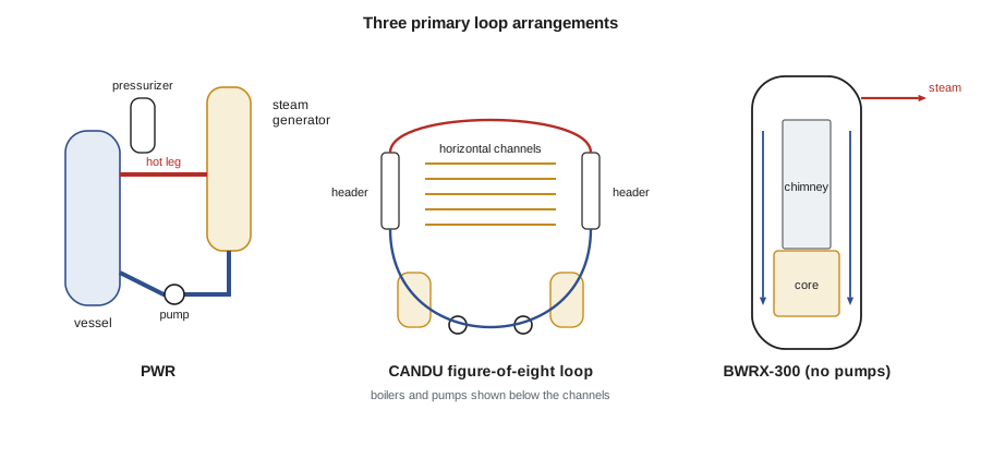
A large PWR has two to four loops connected to one reactor vessel. Coolant at about 15.5 MPa leaves the vessel through a hot leg at about 325 °C, flows through the tubes of a vertical U-tube steam generator, returns through a reactor coolant pump and enters the vessel through a cold leg at about 290 °C. It flows down the downcomer between the vessel wall and the core barrel, turns in the lower plenum, rises through the core and leaves through the upper plenum. One pressurizer, connected to a hot leg, holds a steam bubble above water, with electric heaters to raise pressure and a spray from a cold leg to lower it. Its volume of tens of cubic meters absorbs swells and shrinks of the coolant as its average temperature changes.
The pressure is chosen high enough to keep the bulk coolant subcooled, with saturation at 15.5 MPa near 345 °C, and low enough that the vessel and piping walls are practical to build. Coolant temperatures are limited by DNBR margin at the top of the hot channel and by the thermodynamic efficiency wanted on the secondary side. The secondary side of each steam generator boils feedwater to produce saturated steam at about 6 to 7 MPa, which drives the turbine.
The CANDU heat transport system
A CANDU reactor has hundreds of horizontal fuel channels, each a zirconium-niobium pressure tube inside a calandria tube that passes through the low-pressure moderator tank. The channels are connected by individual feeder pipes to inlet and outlet headers. In a large unit, the channels are split into two loops, and each loop is arranged in a figure of eight: coolant flows through half the channels of the loop in one direction, through a steam generator and pump, then through the other half of that loop's channels in the opposite direction, through a second steam generator and pump, and back. Adjacent channels therefore carry flow in opposite directions, which evens out the axial power and burnup distribution across the core. Heavy water coolant enters the channels at about 265 °C and leaves at about 310 °C, at an outlet header pressure of about 10 MPa, and a pressurizer connected to the outlet headers controls pressure.
Because the moderator is a separate tank at low pressure and about 70 °C, cooled by its own heat exchangers, the CANDU coolant system does not have to carry moderator heat, and in some severe accidents the moderator can act as a heat sink around the channels. Lesson 11 returns to that role.
Boiling water reactors and the BWRX-300
In a boiling water reactor there is no separate steam generator: the coolant boils in the core at about 7 MPa and the steam goes directly to the turbine. Large BWRs recirculate water through the core with jet pumps or internal pumps, and recirculation flow is used to control power. The BWRX-300 takes a simpler approach. It has no recirculation pumps at all. Water boils in the core, the steam-water mixture rises through a tall chimney above the core, separators and dryers at the top remove the water, and the denser water outside the chimney, in the downcomer, flows back down to the core inlet. The density difference between the downcomer and the chimney drives the flow by natural circulation, Lesson 10's subject. The design produces about 300 MW of electricity and relies on passive systems, including isolation condensers, for decay heat removal.
| Feature | Large PWR | CANDU (large unit) | BWRX-300 |
|---|---|---|---|
| Coolant | light water | heavy water | light water |
| Primary pressure | about 15.5 MPa | about 10 MPa at outlet headers | about 7 MPa |
| Core inlet / outlet | about 290 / 325 °C | about 265 / 310 °C | near saturation, boiling in core |
| Steam supply | U-tube steam generators | steam generators (boilers) | direct from the vessel |
| Core flow driven by | reactor coolant pumps | heat transport pumps | natural circulation |
| Pressure control | pressurizer with heaters and spray | pressurizer and feed and bleed | steam dome, turbine control |
The heat balance
Every loop design starts with a heat balance. The core power must leave in the coolant flow:
and it must cross the steam generator tubes:
where \(\Delta T_{\text{lm}}\) is the log-mean temperature difference between the primary coolant and the boiling secondary side, which is close to a constant temperature. A higher primary flow gives a smaller core temperature rise, which helps DNBR margin, but costs pump power. A larger steam generator area allows a higher secondary steam temperature and so a more efficient turbine cycle, but costs money and space. These trade-offs are the essence of coolant system design.
Worked problem
Flow and steam generator size for one PWR loop
A four-loop PWR produces 3411 MW. Each loop carries a quarter of the power with an inlet of 292 °C and an outlet of 326 °C. Take \(c_p = 5.5\) kJ/kg·K and a secondary saturation temperature of 285 °C. Find the loop flow, the log-mean temperature difference and the product \(UA\) for one steam generator.
Show solution
- Loop power \(= 853\) MW; \(\dot m = 853\times10^{6}/(5500 \times 34) = 4560\) kg/s.
- \(\Delta T_1 = 326 - 285 = 41\) K, \(\Delta T_2 = 292 - 285 = 7\) K; \(\Delta T_{\text{lm}} = (41 - 7)/\ln(41/7) = 19.2\) K.
- \(UA = 853\times10^{6}/19.2 = 44\) MW/K.
Answer: About 4560 kg/s per loop and a steam generator \(UA\) of about 44 MW/K. With an overall coefficient of roughly 6 to 8 kW/m²·K, that needs some 5000 to 7000 m² of tube surface per steam generator.
# Coolant loop heat balance, steam generator UA, and pump affinity laws.
import math
def lmtd(th_in, th_out, tc):
    a, b = th_in - tc, th_out - tc
    return (a - b) / math.log(a / b)
loops = {
  'PWR, one of four loops':       dict(Q=3411e6/4, Tin=292.0, Tout=326.0, cp=5500.0, Tsat=285.0),
  'CANDU, one of two loops':      dict(Q=2650e6/2, Tin=266.0, Tout=310.0, cp=5200.0, Tsat=260.0),
}
for name, d in loops.items():
    m = d['Q'] / (d['cp'] * (d['Tout'] - d['Tin']))
    dT = lmtd(d['Tout'], d['Tin'], d['Tsat'])
    UA = d['Q'] / dT
    print(f"{name}: coolant flow {m:,.0f} kg/s, LMTD {dT:4.1f} K, steam generator UA {UA/1e6:5.1f} MW/K")
# Pump affinity laws: flow ~ N, head ~ N^2, power ~ N^3
Q0, H0, P0 = 6.0, 90.0, 6.5     # m3/s, m, MW (illustrative reactor coolant pump)
for frac in (1.0, 0.9, 0.75):
    print(f"speed {frac:4.2f}: flow {Q0*frac:4.2f} m3/s, head {H0*frac**2:5.1f} m, power {P0*frac**3:4.2f} MW")
# Pressurizer: volume change for a coolant temperature swing (illustrative)
V_rcs, beta = 340.0, 3.0e-3     # m3, 1/K near operating conditions
for dT in (2, 5, 10):
print(f"average coolant temperature +{dT} K -> insurge ~{V_rcs*beta*dT:4.1f} m3")PWR, one of four loops: coolant flow 4,560 kg/s, LMTD 19.2 K, steam generator UA 44.3 MW/K CANDU, one of two loops: coolant flow 5,791 kg/s, LMTD 20.8 K, steam generator UA 63.8 MW/K speed 1.00: flow 6.00 m3/s, head 90.0 m, power 6.50 MW speed 0.90: flow 5.40 m3/s, head 72.9 m, power 4.74 MW speed 0.75: flow 4.50 m3/s, head 50.6 m, power 2.74 MW average coolant temperature +2 K -> insurge ~ 2.0 m3 average coolant temperature +5 K -> insurge ~ 5.1 m3 average coolant temperature +10 K -> insurge ~10.2 m3
Reactor coolant pumps
Reactor coolant pumps are large, vertical, single-stage centrifugal pumps. In a PWR each moves roughly 5 to 6 m³/s against about 80 to 100 m of head and is driven by an electric motor of several megawatts. A heavy flywheel on the shaft extends the coastdown after a loss of electrical power, so that flow falls gradually over tens of seconds, giving time for the reactor to trip and decay heat to fall before natural circulation takes over. Shaft seals, which must hold the full system pressure, are among the most carefully engineered components in the plant; a loss of seal cooling during a station blackout can lead to seal leakage, a scenario safety analysts examine closely. CANDU heat transport pumps are similar in principle, with flywheels and multi-stage mechanical seals.
Pump inlet conditions matter too. The pump must have enough net positive suction head to avoid cavitation, which in a loop near saturation means keeping the pressurizer pressure and the cold leg subcooling within limits. During heat-up and cooldown, procedures keep pressure and temperature inside a defined operating window that protects the pumps and also the reactor vessel against brittle fracture at low temperature.
Pressure control
Primary pressure must stay within a narrow band. If it rises too high, safety valves must open; if it falls too low, the margin to boiling and to DNB shrinks. In a PWR, the pressurizer holds a steam space at saturation; heating the water raises the pressure, spraying cold water into the steam space condenses steam and lowers it. When the average coolant temperature rises, the coolant expands and water surges into the pressurizer, compressing the steam; when it falls, water drains out. The pressurizer level control system adjusts charging and letdown flows to keep the level where it should be. In a CANDU, a pressurizer connected to the outlet headers does a similar job, together with feed and bleed of coolant.
Secondary side and the turbine cycle
Although this course concentrates on the primary side, its limits connect directly to the secondary side. The turbine efficiency of water-cooled reactors, about 33 to 36 percent, is set by the steam conditions the primary side can supply. Raising the primary temperatures would raise efficiency, but DNBR margin, materials and, in a PWR, the pressurizer's saturation margin limit how far that can go. MEC-330 covered the Rankine cycle; here the lesson is that the core's thermal limits are ultimately what cap the cycle's efficiency.
Hana's sketches go up on Rohan's whiteboard next to a photograph of a PWR steam generator being lifted into place during a replacement outage. "Each one is the most important heat exchanger in your life when you are on shift," Rohan says.
Steam generators in more detail
A U-tube steam generator holds several thousand thin-walled tubes of a nickel alloy, typically Alloy 690 in modern units, bent into inverted U shapes and expanded into a thick tubesheet at the bottom. Primary coolant enters a hemispherical head below the tubesheet, flows up one leg of each U and down the other, and leaves through the outlet head. On the secondary side, feedwater mixes with recirculating water from the separators and flows down an annular downcomer, then up around the tubes, where it boils. Cyclone separators and dryers at the top return water and send dry steam to the turbine. The tubes are the thinnest part of the pressure boundary; their integrity is checked by eddy-current inspection in outages, and a tube that fails inspection is plugged, which slightly reduces heat transfer area. Tube rupture is a design basis event in which primary coolant leaks to the secondary side, and operators are trained to isolate the affected steam generator and depressurize the primary below the secondary relief setpoints.
CANDU steam generators, often called boilers, follow the same design principles, with inverted U-tubes, internal preheaters on some designs, and steam drums or integral separators. Darlington's boilers and those of other large CANDU stations are among the largest heat exchangers in Canada.
Worked problem
Effect of plugged tubes on primary temperature
A steam generator with UA = 44 MW/K transfers 853 MW to a secondary side at 285 °C. If 6 percent of its tubes are plugged, reducing UA in proportion, by how much must the log-mean temperature difference rise to transfer the same power?
Show solution
- New \(UA = 0.94 \times 44 = 41.4\) MW/K.
- New \(\Delta T_{\text{lm}} = 853/41.4 = 20.6\) K, compared with 19.4 K before.
Answer: About 1.2 K higher. The plant can either accept slightly higher primary temperatures, which uses thermal margin, or lower the secondary steam pressure, which reduces turbine output a little.
Summary and key terms
- The coolant system carries heat, controls pressure and temperature, confines radioactive coolant and supports safety systems.
- PWRs run at about 15.5 MPa with subcooled coolant, U-tube steam generators and a pressurizer.
- CANDU heat transport systems use heavy water at about 10 MPa in figure-of-eight loops through horizontal channels.
- BWRs boil in the core and send steam directly to the turbine; the BWRX-300 circulates by natural circulation.
- Heat balances link flow, temperature rise and steam generator size through Q = ṁcₚΔT and Q = UAΔT_lm.
- Pump coastdown, net positive suction head and pressure control are central to safe operation.
- Primary heat transport system
- The CANDU name for the reactor coolant system.
- Pressurizer
- A vessel with a steam space used to control primary system pressure.
- Figure-of-eight loop
- A CANDU loop arrangement in which coolant passes through two banks of channels in opposite directions.
- Downcomer
- The annular region between vessel wall and core barrel through which coolant flows to the core inlet.
- Log-mean temperature difference
- The effective temperature difference for heat exchanger sizing.
- Coastdown
- The gradual reduction of pump flow after loss of power, extended by a flywheel.
Practice problems
Work each problem on paper first, then reveal the answer to check.
A loop carries 800 MW with ΔT = 35 K and cp = 5.5 kJ/kg·K. What is the flow?
Show answer
\(800\times10^{6}/(5500\times35) \approx 4160\) kg/s.
Why do adjacent CANDU channels carry flow in opposite directions?
Show answer
The figure-of-eight loop arrangement evens out axial power and burnup across the core.
What drives core flow in the BWRX-300?
Show answer
The density difference between the downcomer and the two-phase chimney: natural circulation.
What does a pump flywheel accomplish?
Show answer
It extends flow coastdown after loss of power so the core stays cooled while the reactor trips.
How does pressurizer spray lower pressure?
Show answer
Cold water condenses steam in the steam space, lowering the saturation pressure.
Lesson quiz · 5 questions
Score 60% or more to complete this lesson.
Create a free account to save your progress, take quizzes and earn a certificate.