
NUC-330 · Lesson 4 of 12 · 23 min
Single-phase flow in channels
"Heat transfer gets the attention," Rohan says, "but flow is what keeps the heat transfer coefficient up, and flow is set by pressure drop." He hands Hana a pump curve and a sketch of the core, and asks her two questions: how much of the pump head is spent getting coolant through the fuel, and what happens to the flow in one channel if its resistance rises by ten percent.
The four parts of pressure drop
For steady flow up or along a heated channel, the momentum equation gives the pressure change as the sum of four terms:
Each is worth understanding separately, because each responds differently to design choices and to changes in operating conditions.
Friction
Wall friction in a channel of length \(L\) and hydraulic diameter \(D_h\) is given by the Darcy-Weisbach equation, written in terms of mass flux \(G\) and density \(\rho\):
The Darcy friction factor \(f\) depends on the Reynolds number and the relative roughness. For smooth channels in turbulent flow, the McAdams form \(f = 0.184\,\mathrm{Re}^{-0.2}\) is a convenient estimate over the range of reactor Reynolds numbers; the Colebrook equation and the Moody chart from MEC-270 cover rough walls. Rod bundles have friction factors a few percent different from tubes at the same hydraulic diameter, and designers use bundle-specific correlations from tests.
Form losses
Abrupt changes in geometry, such as spacer grids, bundle junctions, inlet nozzles, orifices, end fittings and bends, cause local losses expressed with a loss coefficient \(K\):
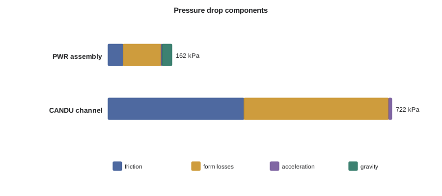
In a PWR assembly the spacer grids, typically eight or more along the length, and the top and bottom nozzles together cause more pressure drop than wall friction. Grid loss coefficients depend on the grid design and on whether it carries mixing vanes; values around 0.5 to 1.2 per grid are typical. In a CANDU channel, the junctions between twelve or thirteen bundles, the end fittings and the shield plugs add form losses, and the feeder pipes connecting each channel to the headers add more.
Acceleration and gravity
As coolant is heated its density falls, so for a constant mass flux its velocity rises. The momentum needed to accelerate it shows up as a pressure drop:
For single-phase liquid this is small, a few kilopascals. In two-phase flow, where density falls by a factor of ten or more, it becomes important. The gravity term is the hydrostatic head of the coolant column,
which in a vertical PWR core of 3.66 m adds about 25 kPa. CANDU channels are horizontal, so gravity does not act along the channel, but it does act in the vertical feeders and the steam generators, and it is what drives natural circulation in Lesson 10.
Worked problem
Pressure drop through a PWR assembly
Water flows up a PWR assembly at \(G = 3600\) kg/m²·s, entering at 745 kg/m³ and leaving at 660 kg/m³. The hydraulic diameter is 11.8 mm, the length 3.66 m and the viscosity \(8.6\times10^{-5}\) Pa·s. Eight spacer grids each have \(K = 1.0\), and the nozzles add \(K = 2.5\) in total. Estimate each component.
Show solution
- Mean density \(\bar\rho = 702\) kg/m³; \(G^{2}/(2\bar\rho) = 9230\) Pa.
- \(\mathrm{Re} = 3600 \times 0.0118/8.6\times10^{-5} = 4.9\times10^{5}\), so \(f = 0.184 \times (4.9\times10^5)^{-0.2} = 0.0134\). Friction \(= 0.0134 \times 3.66/0.0118 \times 9230 = 38\) kPa.
- Form \(= 10.5 \times 9230 = 97\) kPa.
- Acceleration \(= 3600^{2}(1/660 - 1/745) = 2\) kPa; gravity \(= 702 \times 9.81 \times 3.66 = 25\) kPa.
Answer: About 160 kPa in total, of which form losses are about 60 percent. Improving grid design is one of the most effective ways to lower core pressure drop.
# Single-phase pressure drop budget for a heated channel: friction, form, acceleration, gravity.
import math
def f_smooth(Re):                       # McAdams-type smooth-tube friction factor (Darcy)
    return 0.184 * Re ** -0.2
def dp_channel(G, Dh, L, rho_in, rho_out, mu, K_total, dz):
    rho_m = 0.5 * (rho_in + rho_out)
    Re = G * Dh / mu; f = f_smooth(Re)
    fric = f * L / Dh * G**2 / (2 * rho_m)
    form = K_total * G**2 / (2 * rho_m)
    acc = G**2 * (1 / rho_out - 1 / rho_in)
    grav = rho_m * 9.81 * dz
    return Re, f, fric, form, acc, grav
cases = {
  'PWR assembly (vertical, 3.66 m, 8 grids)': (3600.0, 11.8e-3, 3.66, 745.0, 660.0, 8.6e-5, 8 * 1.0 + 1.5 + 1.0, 3.66),
  'CANDU channel (horizontal, 12 bundles)':   (7000.0, 7.4e-3, 5.94, 790.0, 700.0, 9.5e-5, 12 * 0.6 + 4.0, 0.0),
}
for name, a in cases.items():
    Re, f, fr, fo, ac, gr = dp_channel(*a)
    tot = fr + fo + ac + gr
    print(f"{name}\n  Re = {Re:,.0f}, f = {f:.4f}")
    for lab, v in (('friction', fr), ('form', fo), ('acceleration', ac), ('gravity', gr)):
        print(f"  {lab:12s} {v/1000:7.1f} kPa  ({100*v/tot:4.1f} %)")
    print(f"  total        {tot/1000:7.1f} kPa")
# Parallel channels sharing a header-to-header drop: flow scales roughly as sqrt(dP/K)
dP = 1.0
for K in (1.0, 1.1, 1.25):
print(f"relative resistance {K:4.2f} -> relative flow {math.sqrt(dP/K):5.3f}")PWR assembly (vertical, 3.66 m, 8 grids) Re = 493,953, f = 0.0134 friction 38.2 kPa (23.5 %) form 96.9 kPa (59.6 %) acceleration 2.2 kPa ( 1.4 %) gravity 25.2 kPa (15.5 %) total 162.6 kPa CANDU channel (horizontal, 12 bundles) Re = 545,263, f = 0.0131 friction 346.0 kPa (47.9 %) form 368.3 kPa (51.0 %) acceleration 8.0 kPa ( 1.1 %) gravity 0.0 kPa ( 0.0 %) total 722.3 kPa relative resistance 1.00 -> relative flow 1.000 relative resistance 1.10 -> relative flow 0.953 relative resistance 1.25 -> relative flow 0.894
Parallel channels and flow distribution
A reactor core is a set of channels in parallel. In a PWR, every assembly sees the same pressure difference between the lower and upper plena. In a CANDU, every channel connected to the same pair of headers sees the same header-to-header pressure difference. Flow divides among the channels so that each one's pressure drop equals that common value. Since pressure drop varies roughly with the square of flow, a channel with a resistance coefficient 10 percent higher than its neighbors carries about 5 percent less flow, and one 25 percent higher about 11 percent less.
This matters because heat transfer and critical heat flux depend on flow. In an open PWR lattice the effect is softened, because cross-flow can redistribute coolant between assemblies, but designers still check inlet flow maldistribution caused by the lower plenum geometry. Typical analyzes assume the hot assembly receives a few percent less flow than average.
A CANDU reactor, the Canadian heavy water design, shows the opposite extreme. Each channel is closed and has its own feeder pipes, chosen so that each channel receives flow matched to its expected power, with the most flow to the high-power center channels.
Pump head and the system curve
The reactor coolant pumps supply the pressure rise that drives all of these losses around the loop: the core, the steam generator tubes, the hot and cold leg piping and fittings. The operating point is where the pump head curve crosses the system resistance curve, exactly as in MEC-370. In a large PWR the core accounts for roughly a quarter to a third of the loop pressure drop; the steam generators take a similar share. Each reactor coolant pump in a four-loop plant moves several cubic meters of water per second against a head of order 80 to 100 meters, drawing several megawatts of electrical power, and most of that energy ends up as heat in the coolant, which the steam generators remove.
The flow must be high enough to give the heat transfer and critical heat flux margins the design needs, but every extra unit of flow costs pumping power, which rises with the cube of flow. Designers therefore look for low-loss grids and fittings and for core designs that need less flow for the same margin.
Flow measurement and channel temperatures
Total loop flow in a PWR is measured with elbow taps or venturis and checked periodically by a precision calorimetric heat balance on the secondary side, which gives the core power and, through the core temperature rise, the flow. In a CANDU, many channels have outlet temperature measurements, and selected channels have flow measurements, which together allow the operator to infer channel powers and flows. These measurements are used to confirm the design assumptions behind thermal limits.
Laminar flow and low-flow conditions
At full power, reactor coolant flow is strongly turbulent. During startup, shutdown, natural circulation and some accidents, flow rates can be low enough that the Reynolds number falls toward the laminar range. Friction then follows \(f = 64/\mathrm{Re}\) for round tubes, with different constants for bundles, and heat transfer coefficients fall sharply. Thermal-hydraulic codes switch correlations as conditions change, and the transitions are one of the areas analysts examine carefully when comparing codes with tests.
Hana finishes the week with a single-page budget for the PWR loop and a second for one CANDU channel. Rohan circles the form-loss line on both. "That is where the engineers who design fuel bundles and grids earn their keep," he says.
Typical loss coefficients
| Feature | Typical K (based on local dynamic pressure) | Notes |
|---|---|---|
| PWR spacer grid without mixing vanes | 0.5 to 0.8 | depends on grid strap thickness and blockage |
| PWR spacer grid with mixing vanes | 0.9 to 1.3 | more loss, better mixing and critical heat flux |
| Bottom nozzle and debris filter | 1 to 3 | filters trap debris that could fret rods |
| CANDU bundle junction | about 0.4 to 0.8 | depends on element alignment between bundles |
| CANDU end fitting and shield plug | several | large share of channel loss |
| 90 degree elbow in piping | 0.2 to 0.4 | long-radius bends are lower |
Flow-induced vibration and fretting
High coolant velocities are good for heat transfer but can make fuel rods, bundles and steam generator tubes vibrate. Turbulent buffeting, vortex shedding and, in tube bundles exposed to cross-flow, fluid-elastic instability can all excite vibration. Over months, a rod vibrating against a spacer grid spring or a debris particle can wear through its sheath; fretting by debris has been one of the leading causes of fuel failures in light water reactors, which is why debris filters were added to bottom nozzles. In CANDU channels, bundles sit on the bottom of the pressure tube and their bearing pads are designed to resist wear as coolant flows past at several meters per second. Hydraulic design therefore includes vibration and wear testing in flow loops, alongside pressure drop and heat transfer tests.
Feeder pipes and aging
Each CANDU channel connects to the headers through inlet and outlet feeder pipes, typically carbon steel, several meters long and with several bends. In some reactors, outlet feeders have thinned over time by flow-accelerated corrosion, where fast-moving, slightly two-phase water dissolves the protective oxide layer. Feeder thinning slightly changes flow resistance and, more importantly, is a pressure boundary integrity issue that stations inspect and manage. It is another reminder that the hydraulic behavior of a heat transport system changes over its decades of service.
Worked problem
Flow in a channel with a partly blocked inlet
Two parallel channels share a header-to-header pressure difference. Channel A has a total resistance coefficient \(K_A = 20\), referred to its flow area. A foreign object partly blocks channel B's inlet, adding \(\Delta K = 4\). Estimate channel B's flow relative to channel A.
Show solution
- Both channels have the same \(\Delta p\), so \(K_A \dot m_A^{2} = K_B \dot m_B^{2}\).
- \(\dot m_B / \dot m_A = \sqrt{20/24} = 0.913\).
Answer: Channel B carries about 9 percent less flow. For a high-power channel, a reduction of that size could erase a significant part of its critical power margin, which is why foreign material exclusion is taken so seriously during maintenance.
How pressure drop data are obtained
Loss coefficients and friction factors for real fuel are measured, not calculated. Vendors build full-scale or partial-length bundles and test them in hydraulic loops at a range of flows and temperatures, often first in cold water and then in heated loops at reactor pressure. The tests give the pressure drop of each grid, nozzle and bundle junction and the overall bundle friction factor, which designers fit into correlations. When a new fuel design is introduced into a core that still holds older fuel, the two designs must be hydraulically compatible: if the new assemblies had much higher resistance, coolant would bypass them in favor of the old ones, lowering the flow, and the margin, in the new fuel. This mixed-core analysis is a standard part of any fuel transition.
Uncertainties matter too. A loss coefficient known to within 5 percent gives a flow uncertainty of about 2.5 percent, which feeds directly into the heat transfer and critical heat flux margins of later lessons. Rohan's group carries these uncertainties through every analysis rather than treating the nominal values as exact.
Summary and key terms
- Pressure drop has friction, form, acceleration and gravity parts.
- Friction follows Darcy-Weisbach with a Reynolds-number-dependent friction factor; form losses use loss coefficients.
- In PWR assemblies, spacer grids and nozzles cause most of the drop; CANDU channels have large friction and junction losses.
- Acceleration losses are small in single-phase flow and large in two-phase flow; gravity acts only on vertical sections.
- Parallel channels share a pressure difference, so a channel with higher resistance receives less flow.
- Pump operating points are set by the pump curve and the loop system curve; pumping power rises with the cube of flow.
- Darcy friction factor
- The dimensionless coefficient in the Darcy-Weisbach equation for wall friction.
- Loss coefficient
- The ratio of a local pressure loss to the dynamic pressure \(G^2/2\rho\).
- Acceleration pressure drop
- Pressure change needed to accelerate coolant as its density falls.
- Plenum
- A large volume above or below the core from which channels draw or into which they discharge.
- Header
- In a CANDU, a large pipe connecting many feeders to the rest of the heat transport loop.
Practice problems
Work each problem on paper first, then reveal the answer to check.
Doubling the mass flux in a channel changes friction pressure drop by roughly what factor?
Show answer
About \(2^{1.8} \approx 3.5\), since f falls slightly as Re rises.
A grid has K = 0.9 and G²/2ρ = 9 kPa. What is its pressure drop?
Show answer
About 8 kPa.
Which pressure drop component is absent along a horizontal CANDU channel?
Show answer
Gravity.
A channel's resistance coefficient is 21 percent above its neighbors'. Estimate its relative flow.
Show answer
\(1/\sqrt{1.21} \approx 0.91\), about 9 percent less flow.
Why does pumping power rise so steeply with flow?
Show answer
Head rises roughly with flow squared, and power is flow times head, giving about flow cubed.
Lesson quiz · 5 questions
Score 60% or more to complete this lesson.
Create a free account to save your progress, take quizzes and earn a certificate.