
NUC-330 · Lesson 12 of 12 · 20 min
Thermal hydraulic codes
In her last fortnight, Rohan gives Hana a capstone task that ties the course together. She is to write a small one-dimensional channel program of her own, check it against hand calculations, and use it to show how a modest power uprate and a small loss of channel flow change the thermal margin of a heated channel. Then she must explain, to a manager who has never run a code, why the group still trusts the industry's validated codes rather than her program. "Writing a code teaches you what every line in a big code is doing," Rohan says. "Validating one teaches you humility."
Why codes are needed
Every lesson so far has used hand calculations or short programs with idealized shapes. Real analyzes must follow thousands of coupled variables: the flow in every channel or subchannel, the void and temperature at every height, the pressure throughout a loop of pumps, pipes and steam generators, the fuel temperatures that feed reactivity, the operation of valves and control systems, and all of it changing in time. Thermal hydraulic codes solve the conservation equations for mass, momentum and energy numerically on a network of control volumes, with closure relations, the correlations of this course, for friction, heat transfer, interfacial exchange and critical heat flux.
The hierarchy of codes
| Code type | What it represents | Examples | Typical use |
|---|---|---|---|
| System codes | the whole plant as a network of one-dimensional volumes and junctions | RELAP5, TRACE in the United States; CATHENA for CANDU in Canada | transients and LOCAs |
| Subchannel codes | one assembly or bundle as many interconnected subchannels | COBRA, VIPRE; ASSERT for CANDU bundles | DNBR, dryout, mixing |
| Fuel performance codes | one fuel rod or element in detail | FRAPCON, FRAPTRAN; ELESTRES, ELOCA for CANDU | fuel temperatures, gas release, sheath strain |
| Containment codes | containment atmosphere and structures | lumped-parameter and multi-compartment codes | pressure and hydrogen |
| Computational fluid dynamics | three-dimensional flow fields | general-purpose CFD codes | mixing, plena, local phenomena |
System codes trade spatial detail for scope. A plant model may have a few hundred to a few thousand volumes. The two-fluid models in modern system codes, such as RELAP5 and TRACE, solve separate mass, momentum and energy equations for liquid and vapor, with interfacial terms coupling them; this allows them to represent slip, counter-current flow and non-equilibrium. CANDU-specific codes such as CATHENA include models for horizontal channels, stratification, feeders and headers. Subchannel codes resolve a single assembly in detail, and are typically driven by boundary conditions from a system code. Fuel performance codes provide the gap conductance and stored energy that system codes need. CFD is increasingly used for specific questions, such as mixing in plena or around spacer grids, where one-dimensional models are inadequate.
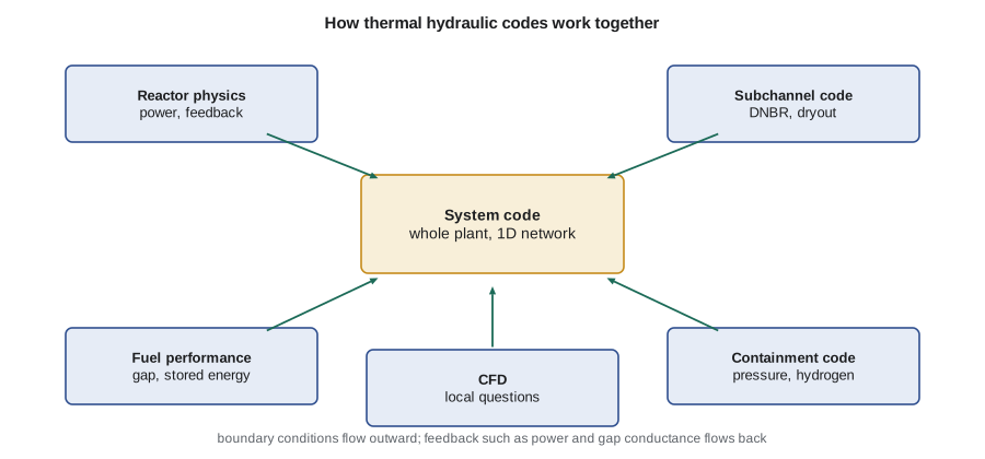
What a code does at each step
Hana's program captures the essence of a one-dimensional channel model. The channel is divided into nodes. At each time step, or for a steady state in a single pass, the program:
| Step | Equation or model | Lesson |
|---|---|---|
| Add heat to the coolant | h_{i+1} = h_i + q'Δz / ṁ | 3 |
| Find quality and void | x_e from enthalpy; void from a slip or drift-flux model | 5 |
| Find mixture density and pressure drop | friction with a two-phase multiplier, form, acceleration, gravity | 4, 5 |
| Find the wall temperature | single-phase convection or a boiling correlation | 3, 6 |
| Find the fuel temperatures | gap, sheath and pellet resistances | 2 |
| Check margin | local CHF or critical power ratio | 7 |
A real system code adds the momentum equation with its time derivative, solves all the volumes simultaneously with an implicit or semi-implicit method, switches flow regimes and correlations as conditions change, and couples to control systems and point or three-dimensional kinetics. But the structure is the same.
# A tiny one-dimensional channel code: march enthalpy, find quality, void, pressure drop,
# clad temperature and a margin to an illustrative CHF fit, node by node.
import math
def run(P_ch, G, L, A, Dh, Pheat, h_in, p_MPa=10.0, N=12):
    h_f, h_fg, rho_f, rho_g, cp, k, mu = 1.408e6, 1.317e6, 690.0, 55.5, 6100.0, 0.50, 8.6e-5
    dz = L / N; h = h_in; dp = 0.0; out = []
    for i in range(N):
        z = (i + 0.5) * dz
        shape = math.sin(math.pi * z / L) * math.pi / 2        # peak 1.57 x average
        qpp = P_ch / (Pheat * L) * shape                        # local heat flux, W/m2
        h += qpp * Pheat * dz / (G * A)
        x = (h - h_f) / h_fg
        xa = max(x, 0.0)
        alpha = 0.0 if xa == 0 else 1 / (1 + (1 - xa) / xa * rho_g / rho_f * 1.5)
        rho_m = alpha * rho_g + (1 - alpha) * rho_f
        Re = G * Dh / mu; f = 0.184 * Re ** -0.2
        dp += f * dz / Dh * G**2 / (2 * rho_m)
        Tb = 311.0 if x >= 0 else 311.0 + (h - h_f) / cp      # 311 C saturation at 10 MPa
        hw = 0.023 * Re**0.8 * (cp * mu / k)**0.4 * k / Dh
        Tw = Tb + qpp / hw if x < 0 else 311.0 + 6.0
        chf = max(0.3e6, 3.0e6 * (G / 3000) ** 0.4 * (1 - 1.5 * x))
        out.append((z, x, alpha, Tw, chf / qpp))
    return out, dp
for label, P in (('nominal 6.5 MW channel', 6.5e6), ('aged channel at 6.5 MW, 6 % less flow', 6.5e6)):
    G = 7000.0 if 'nominal' in label else 6580.0
    res, dp = run(P, G, 5.94, 3.4e-3, 7.4e-3, 37 * math.pi * 13.1e-3, 1.155e6)
    mr = min(r[4] for r in res)
    print(f"{label}: exit quality {res[-1][1]:+.3f}, exit void {res[-1][2]:.2f}, friction dp {dp/1000:5.0f} kPa, min CHF ratio {mr:.2f}")
for z, x, a, Tw, r in run(6.5e6, 7000.0, 5.94, 3.4e-3, 7.4e-3, 37*math.pi*13.1e-3, 1.155e6)[0][::3]:
print(f" z = {z:4.2f} m: x = {x:+.3f}, void {a:.2f}, wall {Tw:5.1f} C, CHF ratio {r:4.2f}")nominal 6.5 MW channel: exit quality +0.016, exit void 0.12, friction dp 373 kPa, min CHF ratio 4.11 aged channel at 6.5 MW, 6 % less flow: exit quality +0.029, exit void 0.20, friction dp 342 kPa, min CHF ratio 3.96 z = 0.25 m: x = -0.189, void 0.00, wall 272.5 C, CHF ratio 36.66 z = 1.73 m: x = -0.140, void 0.00, wall 294.2 C, CHF ratio 5.69 z = 3.22 m: x = -0.061, void 0.00, wall 314.6 C, CHF ratio 4.11 z = 4.70 m: x = +0.002, void 0.02, wall 317.0 C, CHF ratio 6.11
Verification and validation
A code is useful only if it is right for the problem. Two separate questions apply. Verification asks whether the code solves its equations correctly: the numerical methods converge, the coding has no errors, and results agree with analytical solutions where they exist. Validation asks whether the equations and correlations represent reality: the code is compared with experiments that span the conditions of the application. Validation uses separate effects tests, which isolate one phenomenon, such as critical heat flux in a heated bundle or critical flow through a break, and integral tests, which reproduce a whole system's behavior in a scaled facility.
In the United States, programs such as the LOFT and Semiscale facilities at the Idaho National Laboratory, and later scaled integral facilities for passive plants, produced integral LOCA and transient data, and separate effects programs studied reflood, critical flow and CHF. International programs, such as those coordinated by the OECD Nuclear Energy Agency, provide shared data for codes of all reactor types.
Validation leads to a statement of code uncertainty for each important output, such as peak cladding temperature or minimum critical power ratio. The Code Scaling, Applicability and Uncertainty (CSAU) methodology, developed for the NRC in the late 1980s, set out a structured approach: identify the important phenomena for the scenario, often through a phenomena identification and ranking table (PIRT); confirm the code can model them at plant scale; and quantify the uncertainties by comparison with data. Best-estimate plus uncertainty methods, now used in both countries, apply this approach to licensing.
Uncertainty propagation
In a BEPU analysis, uncertain inputs, such as decay heat, gap conductance, break discharge coefficient, CHF and the heat transfer correlations, are each assigned a probability distribution. The code is then run many times with inputs sampled from the distributions. A common approach uses order statistics, Wilks' formula, which shows that 59 random runs are enough for the highest result to bound the 95th percentile with 95 percent confidence for a single output, and that more runs are needed for several outputs or higher-order bounds. The result is a statement such as "the 95th percentile peak cladding temperature, at 95 percent confidence, is 1050 °C", compared with the limit.
Worked problem
How many runs?
An analyst wants a one-sided bound at the 95th percentile with 95 percent confidence on one output, using the largest of N code runs. How many runs are needed?
Show solution
- The chance that all N runs fall below the 95th percentile is \(0.95^{N}\).
- For 95 percent confidence that at least one run exceeds it, \(1 - 0.95^{N} \ge 0.95\).
- \(0.95^{N} \le 0.05\) gives \(N \ge \ln 0.05 / \ln 0.95 = 58.4\).
Answer: 59 runs, the familiar first-order Wilks number. Using the second-highest run, which is less sensitive to outliers, requires 93.
User effects and quality assurance
Codes do not run themselves. The same code, applied to the same problem by different analysts, can give noticeably different answers, because of choices of nodalization, options, time step, initial conditions and boundary conditions. International benchmark exercises have repeatedly shown such user effects. Good practice therefore includes documented nodalization guidelines, independent review of input decks, sensitivity studies and comparison with simpler hand calculations, which is exactly why Rohan insisted Hana learn to estimate everything by hand first. In both countries, safety analysis software and the analyzes done with it are governed by quality assurance requirements, such as those in CSA N286.7 in Canada and in Appendix B to 10 CFR Part 50 in the United States.
The capstone result
Hana's program runs a nominal high-power channel and the same channel with 6 percent less flow, standing in for a combination of slightly higher power and flow allowances in the uprate case. The reduced flow raises the exit quality from about 1.6 to 2.9 percent and the exit void from about 0.12 to 0.20, and lowers the minimum margin to her illustrative CHF fit by about 4 percent. She presents the result with three caveats: her CHF fit is a teaching function, her single channel ignores subchannel mixing, and her result needs confirming with the licensed subchannel and system codes. Rohan's group runs those codes; their answer is consistent with hers in direction and similar in size, and it feeds the uprate margin table.
| Quantity | Nominal channel | Reduced-flow channel |
|---|---|---|
| Mass flux (kg/m²·s) | 7000 | 6580 |
| Exit equilibrium quality | +0.016 | +0.029 |
| Exit void fraction | 0.12 | 0.20 |
| Friction pressure drop (kPa) | about 373 | about 342 |
| Minimum ratio to illustrative CHF fit | 4.11 | 3.96 |
"Your program is about two hundred lines," Rohan tells her at the review. "The codes we use are a few hundred thousand, plus decades of validation. Yours got the right answer because the problem was simple and you checked it by hand. When the problem is a LOCA, nobody's two hundred lines will do. But you now know what the big codes are doing, and you will be the person in the room who asks whether their answer makes physical sense."
Looking ahead
This course has followed heat from the fission fragment to the steam generator and back to the core in natural circulation and accidents. Later courses build on it: NUC-350 couples it to core design and fuel management, NUC-360 to complete reactor systems, NUC-410 to safety analysis and probabilistic assessment, and NUC-430 to control and instrumentation. Hana returns to the core physics group with a better sense of what her neutron flux maps mean for the fuel, which is exactly what Dr. Vasquez had in mind when she sent her to Rohan.
Coupled codes
Many transients involve strong feedback between thermal hydraulics and neutronics: a BWR stability event, a PWR main steam line break with return to power, or a CANDU loss of regulation. For these, analysts couple a system code to a three-dimensional kinetics code, so that the power distribution responds to local void, coolant temperature and fuel temperature as they evolve. Coupled calculations are demanding, both in computing and in validation, and their use has grown as computers have become faster. Fuel performance codes are also increasingly coupled, so that gap conductance and stored energy change consistently during a transient.
Summary and key terms
- Thermal hydraulic codes solve mass, momentum and energy conservation on networks of control volumes with closure correlations.
- System, subchannel, fuel performance, containment and CFD codes work together, exchanging boundary conditions.
- Verification checks the numerics; validation compares with separate effects and integral tests.
- CSAU and BEPU methods quantify code uncertainty; 59 runs give a first-order 95/95 bound on one output.
- User effects are real; nodalization guidelines, review and hand checks guard against them.
- A simple channel code captures the structure of large codes and is a powerful check on their results.
- System code
- A code representing a whole plant as a network of one-dimensional volumes and junctions.
- Subchannel code
- A code representing one fuel assembly or bundle as many interconnected subchannels.
- Verification
- Confirming that a code solves its equations correctly.
- Validation
- Confirming, by comparison with experiments, that a code represents reality for its application.
- PIRT
- A phenomena identification and ranking table, used to focus validation on what matters.
- Wilks' formula
- An order-statistics result giving the number of random runs needed for a tolerance bound.
Practice problems
Work each problem on paper first, then reveal the answer to check.
What is the difference between verification and validation?
Show answer
Verification checks the code solves its equations correctly; validation checks the equations represent reality.
How many runs give a 95/95 bound using the second-highest result?
Show answer
93.
Give one example each of a separate effects test and an integral test.
Show answer
A CHF test on a heated bundle; a scaled whole-loop LOCA test such as RD-14M or LOFT.
Why do analysts compare code results with hand calculations?
Show answer
To catch input and modeling errors and to confirm the result makes physical sense.
Name a CANDU system thermal hydraulic code.
Show answer
CATHENA.
Lesson quiz · 5 questions
Score 60% or more to complete this lesson.
Create a free account to save your progress, take quizzes and earn a certificate.