
NUC-330 · Lesson 3 of 12 · 22 min
Convection to coolant
With the pellet and sheath understood, Rohan sends Hana to the other side of the wall. "The coolant decides everything we just calculated," he says, "because it fixes the starting temperature. And unlike the pellet, it changes along the channel." Her task this week is to produce, by hand and then in a short program, the coolant, sheath and fuel center temperatures from the bottom to the top of the hottest channel.
The energy balance along a channel
Coolant entering a heated channel at mass flow rate \(\dot m\) and specific enthalpy \(h_{\text{in}}\) picks up all the heat the rod or element delivers. In steady state, an energy balance over a short length \(dz\) gives
so the enthalpy at any height is the inlet enthalpy plus the heat delivered below that height, divided by the flow. For single-phase liquid with roughly constant specific heat, the bulk coolant temperature follows the same integral, \(T_b(z) = T_{\text{in}} + \frac{1}{\dot m c_p}\int q'\,dz\). For a chopped cosine heat shape, the coolant temperature rises slowly at the inlet, fastest at the mid-plane where the heat input peaks, and slowly again near the outlet. Its shape is an S-curve, the integral of a cosine.
The outlet enthalpy rise of the hottest channel is the quantity that the enthalpy rise hot channel factor \(F_{\Delta H}\) from Lesson 1 controls. A channel that produces 55 percent more heat than average, with the same flow, heats its coolant 55 percent more. If its coolant approaches saturation, boiling and critical heat flux limits come into play.
Heat transfer coefficients
Between the sheath surface and the bulk coolant there is a thin boundary layer through which heat moves by conduction and turbulent mixing. Its effect is captured in a heat transfer coefficient \(h\), defined by Newton's law of cooling:
For turbulent forced convection of a liquid in a tube, the most widely taught correlation is Dittus-Boelter:
with the Reynolds number \(\mathrm{Re} = G D_h/\mu\) based on the mass flux \(G\) and the hydraulic diameter \(D_h\). MEC-340 introduced it with its limits: it applies to fully developed turbulent flow with moderate property variation, and it can be in error by 10 to 25 percent. The Gnielinski correlation, also from MEC-340, is more accurate over a wider range, and the Petukhov form underlies it.
Rod bundles and the hydraulic diameter
Reactor coolant does not flow in tubes; it flows parallel to bundles of rods. The hydraulic diameter of the flow passage is
For a square-pitch lattice with pitch \(P\) and rod diameter \(D\), the flow area of one unit cell, or subchannel, is \(P^{2} - \pi D^{2}/4\) and its wetted perimeter is \(\pi D\). A typical PWR lattice with \(P = 12.6\) mm and \(D = 9.5\) mm gives \(D_h \approx 11.8\) mm. CANDU bundles sit in round pressure tubes, with 37 elements arranged in rings, and the bundle hydraulic diameter is about 7 to 8 mm.
Tube correlations applied to rod bundles with \(D_h\) are a first approximation. Experiments show that heat transfer in bundles depends on the pitch-to-diameter ratio as well. Weisman's correction for square arrays multiplies the Dittus-Boelter Nusselt number by a factor \(\psi = 1.826\,P/D - 1.0430\), which for \(P/D = 1.33\) is about 1.38. Triangular arrays have their own fit. Rohan reminds Hana that the correction is not a fudge: the flow in a bundle is genuinely more turbulent near the gaps between rods, and mixing vanes on PWR spacer grids and the appendages on CANDU bundles enhance it further.
| Geometry | Approximate hydraulic diameter | Typical mass flux (kg/m²·s) | Typical h (kW/m²·K) |
|---|---|---|---|
| PWR 17×17 subchannel | 11.8 mm | 3000 to 4000 | 35 to 55 |
| BWR bundle (lower part, liquid) | 12 to 14 mm | 1000 to 2000 | 20 to 35 |
| CANDU 37-element bundle | 7 to 8 mm | 6000 to 8000 | 40 to 60 |
| Pool-type research reactor (natural circulation) | several mm to cm | much lower | a few |
Coolant properties
Water at reactor conditions is not the water of a textbook table at 25 °C. At 15.5 MPa and 310 °C its density is about 700 kg/m³, its specific heat about 5.8 kJ/kg·K and its viscosity about one twelfth of the room-temperature value. These changes raise the Reynolds number and the specific heat, which helps, and lower the conductivity somewhat. Properties must be evaluated at the local bulk temperature, and near the outlet of a hot channel they change quickly as the water approaches saturation. Heavy water has a slightly higher density and lower specific heat than light water at the same temperature, and CANDU heat transport systems run at about 10 MPa with an outlet near 310 °C.
Rohan uses the international steam tables, IAPWS-IF97, in the group's codes. Hana's hand calculations use rounded values, which is fine for learning but not for design. Heavy water properties, needed for CANDU analysis, are published separately by IAPWS.
Worked problem
The heat transfer coefficient in a hot PWR subchannel
Water at 310 °C and 15.5 MPa flows through a PWR subchannel with \(P = 12.6\) mm, \(D = 9.5\) mm at \(G = 3600\) kg/m²·s. Take \(\mu = 8.6 \times 10^{-5}\) Pa·s, \(c_p = 5.8\) kJ/kg·K and \(k = 0.54\) W/m·K. Estimate \(h\) with Dittus-Boelter and the Weisman correction, and the film temperature drop at a heat flux of 1.34 MW/m².
Show solution
- \(D_h = 4(12.6^2 - \pi \times 9.5^2/4)/(\pi \times 9.5) = 11.8\) mm.
- \(\mathrm{Re} = 3600 \times 0.0118 / 8.6\times 10^{-5} = 4.9 \times 10^{5}\); \(\mathrm{Pr} = 5800 \times 8.6\times10^{-5}/0.54 = 0.92\).
- Dittus-Boelter (heating, exponent 0.4; the program uses 0.333 for a slightly conservative estimate): \(\mathrm{Nu} \approx 0.023 \times (4.9\times10^5)^{0.8} \times 0.92^{0.4} \approx 790\), and Weisman raises it by 1.38 to about 1090.
- \(h = 1090 \times 0.54 / 0.0118 \approx 50\) kW/m²·K; film drop \(= 1.34\times10^{6}/50\,000 \approx 27\) K.
Answer: About 50 kW/m²·K and a film temperature drop of about 27 K at the hot spot. The coolant boundary layer is a small resistance compared with the gap and pellet.
Temperatures along the channel
Combining the axial energy balance with the radial resistances of Lesson 2 gives temperatures at every height. Three profiles matter. The bulk coolant temperature rises in an S-curve from inlet to outlet. The sheath surface temperature is the bulk temperature plus the film drop, which is largest where the heat flux peaks; their sum peaks downstream of the mid-plane, because the coolant is hotter there. The fuel center temperature is the sheath temperature plus the large pellet and gap drops, which follow the heat flux closely; it peaks close to, but slightly above, the mid-plane.
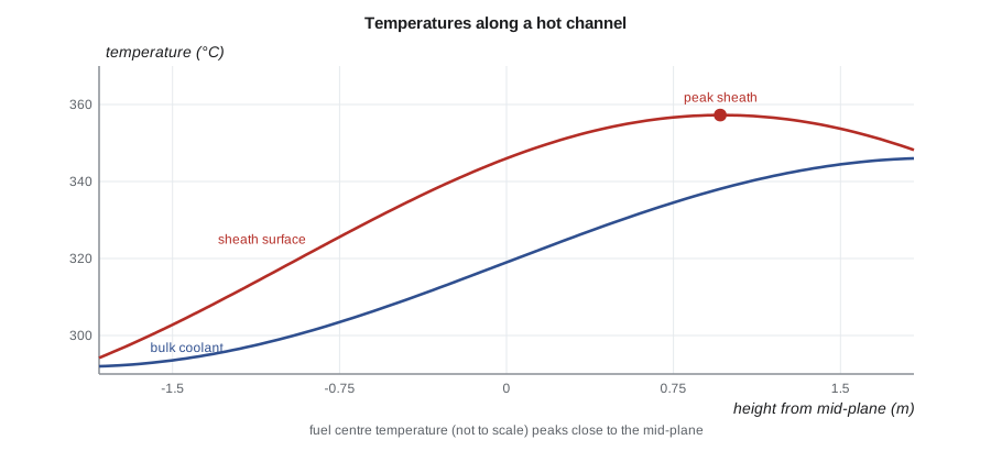
The locations of these peaks have practical consequences. The maximum sheath temperature, which controls corrosion and the onset of boiling, occurs in the upper half of the core in a PWR. The maximum fuel temperature occurs near the middle. Critical heat flux, which depends on both local heat flux and local coolant quality, occurs at yet another place, usually above the mid-plane, as Lesson 7 shows.
A closed-form solution exists for the maximum sheath temperature with a pure cosine heat shape, and every textbook derives it. Rohan prefers the numerical approach. "Real power shapes are never pure cosines," he says. "March up the channel in nodes and you can use any shape the physicists give you."
# Coolant, cladding and fuel center temperatures along a heated channel (chopped cosine power).
import math
def props_water():       # rough properties of light water near 15.5 MPa, 310 C (illustrative)
    return dict(cp=5800.0, k=0.54, mu=8.6e-5, rho=700.0)
w = props_water()
# Hot PWR subchannel (square pitch), illustrative
P, D, L, Le = 12.6e-3, 9.5e-3, 3.66, 3.86
A = P**2 - math.pi * D**2 / 4; Pw = math.pi * D; Dh = 4 * A / Pw
G = 3600.0                         # kg/m2-s
m = G * A
qmax = 40e3                        # W/m peak linear heat rate in the hot rod
Re = G * Dh / w['mu']; Pr = w['cp'] * w['mu'] / w['k']
psi = 1.826 * P / D - 1.0430       # Weisman square-array factor
h = psi * 0.023 * Re**0.8 * Pr**0.333 * w['k'] / Dh
print(f"Dh = {Dh*1000:4.1f} mm, Re = {Re:,.0f}, Weisman factor = {psi:4.2f}, h = {h:,.0f} W/m2-K")
T_in = 292.0
def qz(z): return qmax * math.cos(math.pi * z / Le)
N = 12; dz = L / N; Tb = T_in; peak = (0, None)
for i in range(N):
    z = -L/2 + (i + 0.5) * dz
    Tb += qz(z) * dz / (m * w['cp'])
    Tw = Tb + qz(z) / (math.pi * D * h)
    Tc = Tw + qz(z) * (1/(2*math.pi*D/2*6000) + 1/(4*math.pi*3.0))   # crude gap + fuel, k ~ 3 W/m-K
    if Tw > peak[0]: peak = (Tw, z)
    if i % 2 == 1:
        print(f"z = {z:+5.2f} m: bulk {Tb:5.1f} C, clad surface {Tw:5.1f} C, center ~{Tc:6.0f} C")
print(f"peak clad surface {peak[0]:.1f} C at z = {peak[1]:+.2f} m (downstream of mid-plane)")Dh = 11.8 mm, Re = 493,026, Weisman factor = 1.38, h = 50,745 W/m2-K z = -1.37 m: bulk 296.3 C, clad surface 307.8 C, center ~ 871 C z = -0.76 m: bulk 306.0 C, clad surface 327.5 C, center ~ 1372 C z = -0.15 m: bulk 318.8 C, clad surface 345.0 C, center ~ 1620 C z = +0.46 m: bulk 331.6 C, clad surface 356.2 C, center ~ 1553 C z = +1.07 m: bulk 341.3 C, clad surface 358.3 C, center ~ 1188 C z = +1.68 m: bulk 345.5 C, clad surface 350.9 C, center ~ 613 C peak clad surface 358.5 C at z = +0.76 m (downstream of mid-plane)
Entrance effects, mixing and subchannels
Correlations for fully developed flow underpredict heat transfer near the inlet of a channel and just downstream of spacer grids, where the boundary layer is thin. This is a small benefit that designers often ignore. More important is cross-flow between subchannels. In an open lattice like a PWR assembly, coolant moves sideways between neighboring subchannels through the gaps between rods. A hot subchannel shares some of its heat with cooler neighbors, which lowers its outlet enthalpy below what a closed-channel calculation would predict. Subchannel codes model this mixing explicitly, and it is one source of margin that thermal design takes credit for.
In a CANDU bundle, the closed pressure tube prevents exchange between channels, but subchannels within the bundle mix. As pressure tubes creep and their diameter grows with age, more coolant bypasses the bundle through the gap at the top of the tube. Lesson 8 shows how that aging effect reduces thermal margin.
When the coolant is not water
Most of this course concerns water-cooled reactors, but the same principles apply to other coolants with different numbers. Liquid metals such as sodium have a Prandtl number around 0.005, so heat moves through the boundary layer mostly by conduction and correlations of the Lyon-Martinelli type are used. Gas coolants such as helium have low density and low heat capacity per volume, so they need high velocities and large heat transfer surfaces, and their correlations include strong property-variation corrections. NUC-450 returns to these coolants for advanced reactors.
Fouling, crud and heat transfer surfaces
Clean correlations describe clean surfaces. In service, corrosion products carried by the coolant, mostly iron and nickel oxides from steam generator tubes and piping, deposit on fuel sheaths as crud. A thin, porous crud layer can actually improve heat transfer by providing nucleation sites, but thicker deposits add thermal resistance and trap boron and lithium in light water reactors. In some PWRs, heavy crud in high-power, subcooled-boiling regions has concentrated boron and distorted the axial power shape, an effect called crud-induced power shift, and in extreme cases has led to localized corrosion. Water chemistry programs, coolant pH control and careful core design limit these effects.
On the secondary side, steam generator tube fouling lowers the overall heat transfer coefficient, raises the primary coolant temperatures needed to transfer the same power, and gradually erodes thermal margin. Utilities track fouling by monitoring steam pressure and primary temperatures over time and clean steam generators when needed. CANDU stations follow the same approach for their boilers, and they also monitor reactor inlet header temperature, which creeps upward as boilers foul and pressure tubes age.
Worked problem
Effect of an oxide layer on sheath temperature
A sheath grows a 40 µm zirconium oxide layer with conductivity 2 W/m·K. At a local heat flux of 1.2 MW/m², what extra temperature rise does it add?
Show solution
- For a thin layer, \(\Delta T \approx q'' \delta / k = 1.2\times10^{6} \times 40\times10^{-6} / 2\).
- \(\Delta T \approx 24\) K.
Answer: About 24 K, comparable with the coolant film drop. Oxide growth is one reason sheath temperature limits are checked at end of life as well as at the start.
Summary and key terms
- The coolant enthalpy rises along the channel as the integral of the linear heat rate divided by the flow.
- Newton's law of cooling, \(q'' = h(T_w - T_b)\), defines the heat transfer coefficient.
- Dittus-Boelter with the hydraulic diameter is a first estimate; rod bundles need corrections such as Weisman's factor.
- Coolant properties change strongly with temperature at reactor conditions and must be evaluated locally.
- The bulk temperature rises as an S-curve; peak sheath temperature lies downstream of the mid-plane and peak fuel temperature near it.
- Cross-flow between subchannels lowers hot-subchannel enthalpy; closed CANDU channels mix only within the bundle.
- Bulk temperature
- The mixed-mean temperature of the coolant at a given height.
- Heat transfer coefficient
- The ratio of surface heat flux to the wall-to-bulk temperature difference.
- Hydraulic diameter
- Four times flow area divided by wetted perimeter.
- Subchannel
- The flow area bounded by neighboring rods in a lattice, used as a computational cell.
- Weisman correction
- A factor applied to tube correlations for heat transfer in square or triangular rod arrays.
Practice problems
Work each problem on paper first, then reveal the answer to check.
A channel with flow 0.30 kg/s receives 120 kW. With cp = 5.6 kJ/kg·K, what is the coolant temperature rise?
Show answer
\(120\,000/(0.30 \times 5600) \approx 71\) K.
Find the hydraulic diameter of a square subchannel with P = 14 mm and D = 10 mm.
Show answer
\(4(196 - 78.5)/(31.4) \approx 15\) mm.
If h = 40 kW/m²·K and q'' = 1.2 MW/m², what is the film temperature drop?
Show answer
30 K.
Why is the peak sheath temperature located above the mid-plane?
Show answer
The film drop peaks at the mid-plane, but the coolant keeps heating, so their sum peaks higher up.
Why do subchannel codes give more margin than closed-channel calculations in a PWR?
Show answer
They credit cross-flow mixing that carries heat from the hottest subchannel to its neighbors.
Lesson quiz · 5 questions
Score 60% or more to complete this lesson.
Create a free account to save your progress, take quizzes and earn a certificate.