
LVT-330 · Lesson 2 of 12 · 19 min
NEC Chapter 7 and Chapter 8
Most of what Cobalt Line installs falls under two chapters of the National Electrical Code. Chapter 8 covers communications systems: telephone, data, intercom and similar circuits, cable television and broadband. Chapter 7 holds the special conditions that cover power-limited circuits: Article 725 for Class 2 and Class 3 circuits that power and control security devices, door hardware, sensors, thermostats and many audio outputs, Article 760 for fire alarm circuits and Article 770 for optical fiber. Since the 2023 edition, Article 722 holds the cable requirements shared by power-limited and optical fiber circuits. Greta asks Maya to learn the boundaries of each article first, because the first question on any device is which article it falls under, and every later rule depends on the answer.
What a communication circuit is
The NEC treats communications circuits as circuits that carry voice, audio, video, data, interactive services and outside wiring for fire alarm and burglar alarm, from a communications utility to the customer's equipment, and the premises wiring that connects such equipment. Article 805 covers those circuits, and Article 800 holds the requirements shared by Articles 805, 820, 830 and 840: entrance cables, protection, grounding and bonding, installation in buildings and cable listings. A structured cabling system carrying Ethernet is a communications system under Chapter 8. So is a telephone system and an intercom system wired with communications cable.
Chapter 8 sets rules for the parts of a communications system that matter to safety: protection of conductors that enter from outside and may be exposed to lightning or power contact (800.90), grounding and bonding of protectors and cable shields (800.100), installation of cables in plenums, risers and other spaces (800.113 and 800.154), separation from power conductors and support (805.133 and 800.24), removal of abandoned cable (800.25) and listing of cables (800.179). It does not set rules for the performance of the network.
Class 1 and Class 2 circuits
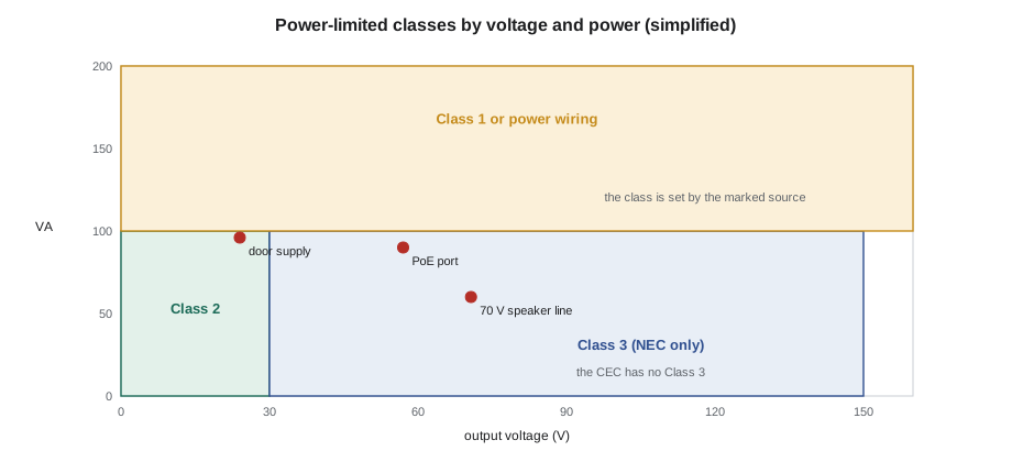
A Class 2 circuit is one supplied by a source whose output is limited, by its design or by overcurrent protection, so that it is safe from fire under normal conditions and from shock. Chapter 9, Tables 11(A) and 11(B), give the limits for sources: for most Class 2 sources, no more than 30 V and 100 VA in dry locations, with tighter current limits at higher voltages. A Class 3 circuit may run at higher voltages, up to 150 V, with power still limited to 100 VA; because shock is possible, Class 3 cable has heavier insulation. A Class 2 or Class 3 power supply is marked, and so are transformers and many devices with power-limited outputs. Because the source is limited, Article 725 allows lighter wiring methods: Class 2 cable without a raceway, smaller conductors and simpler support.
Class 1 circuits are now in Article 724: power-limited Class 1 circuits up to 30 V and 1,000 VA, and Class 1 remote-control and signaling circuits up to 600 V. They are wired like power conductors and must be kept apart from Class 2, Class 3 and communications conductors. Article 726 covers the new Class 4 fault-managed power systems, which deliver larger amounts of power by monitoring the line and shutting down quickly on a fault.
When a circuit stays Class 2
A Class 2 circuit keeps that status only while it is connected to a listed or certified Class 2 source and wired as Class 2. Three common mistakes destroy it:
- Paralleling the outputs of two Class 2 supplies to get more current. The combined source is no longer limited and the circuit is not Class 2 unless the manufacturer's listing allows it.
- Replacing a failed Class 2 supply with an ordinary power supply that has the same voltage. The new supply may deliver far more current into a fault.
- Running Class 2 conductors in the same raceway, box or cable as power or Class 1 conductors without the barrier or separation the code requires. The separation rules are in lesson 5.
Power over Ethernet sits at an interesting boundary. A PoE port is a power-limited source, and when a cable carries both data and more than a small amount of power, the NEC's rules for Class 2 and Class 3 circuits that transmit power and data apply, in 725.144. The table in that section relates conductor size, the number of cables in a bundle and the current per conductor, and allows smaller bundles or cables listed with an -LP marking, such as CL2-LP, for higher currents. As PoE ports deliver up to about 90 W, bundle heating is a real design question. For Cobalt Line, the practical rule is to check 725.144 against the PoE class on the design, and to follow the bundle-size guidance in the specification and in TIA's PoE bulletin.
# Is this circuit power-limited? Simplified screen against NEC class limits (illustrative values)
devices = [  # (name, open-circuit volts, rated VA, source marked as power-limited)
    ("Door controller supply", 27.6, 96, True),
    ("Paralleled pair of 24 V supplies", 27.6, 192, False),
    ("Paging amplifier 70 V output", 70.7, 60, True),
    ("Replacement supply, unmarked", 24.0, 240, False),
    ("PoE port, Type 4", 57.0, 90, True),
]
def classify(v, va, marked):
    if not marked:
        return "not power-limited: treat as Class 1 or power"
    if v <= 30 and va <= 100:
        return "Class 2"
    if v <= 150 and va <= 100 and True:
        return "Class 3"
    return "check the listing and 725.144"
for name, v, va, marked in devices:
print(f"{name:34s} {v:5.1f} V {va:4d} VA -> {classify(v, va, marked)}")Door controller supply 27.6 V 96 VA -> Class 2 Paralleled pair of 24 V supplies 27.6 V 192 VA -> not power-limited: treat as Class 1 or power Paging amplifier 70 V output 70.7 V 60 VA -> Class 3 Replacement supply, unmarked 24.0 V 240 VA -> not power-limited: treat as Class 1 or power PoE port, Type 4 57.0 V 90 VA -> Class 3
The screen is only a first look. The NEC's limits differ for AC and DC, for wet locations and for sources that are inherently limited, and what governs in the end is the listing and marking of the source. The 70 V speaker line shows why: it can fall under Class 2 or Class 3 depending on the amplifier's listing, which decides the cable type.
The structure of Section 60 and Chapter 8
Article 800 is organized roughly in the order a cable meets the rules. Part I holds general requirements, including access to equipment (800.21), mechanical execution of work (800.24), abandoned cables (800.25) and spread of fire (800.26). Part II covers wires and cables outside and entering buildings. Part III covers protection (800.90), Part IV grounding methods (800.100), Part V installation within buildings (800.110 to 800.154) and Part VI listing requirements (800.170 to 800.182). Article 805 then adds the requirements special to communications circuits, such as separation from other systems in 805.133. Article 725 and Article 722 follow a similar pattern for power-limited circuits.
| Part of Article 800 | What it covers |
|---|---|
| Part I General | Access, workmanship, abandoned cable, spread of fire |
| Part II Outside and entrance | Overhead, underground, entrance cables |
| Part III Protection | Primary protectors and their location |
| Part IV Grounding methods | Bonding conductor size, length and connection |
| Part V Installation in buildings | Raceways, plenums, risers, applications |
| Part VI Listing | Cable and raceway markings |
Equipment approval
The NEC requires that communications equipment, power-limited sources and cables be listed where the code says so. Listing means a nationally recognized testing laboratory such as UL Solutions or Intertek has tested the product to a standard and lists it, and the product carries the lab's mark. Cables carry their listing type, such as CMP or CL2R, printed on the jacket, which is what the inspector checks. Equipment from overseas without a recognized listing can be refused even if it works perfectly.
A device-by-device check
On the St. Brendan's east wing, Maya builds a table listing every system the crew installs, the part of the code it falls under, its source and the cable type the design calls for. Sanjay reviews it before ordering. The table catches two issues before any cable is bought: the nurse call vendor's corridor lights are fed from a supply that is not marked Class 2, so their wiring must follow the rules for power wiring unless the vendor supplies a certified Class 2 source; and the access control panels are specified with a battery charger whose output is Class 2 only when the panel is wired as its installation manual shows. Both go back to the design team as questions.
Worked problem
Choosing the right part of the code for a wall of devices
At Juniper Point's lobby, one wall holds a door intercom, a card reader, an electric strike, a camera and a fire alarm pull station. Maya lists the rule set for each.
Show solution
- Door intercom on communications cable to the concierge desk: Article 805.
- Card reader and electric strike, fed from the access control panel's Class 2 outputs: Article 725, with cable listings in Article 722.
- PoE camera on a data outlet: Chapter 8 for the cabling, with 725.144 bundle rules applying to the power it carries.
- Fire alarm pull station: Article 760 and NFPA 72; installed by the fire alarm contractor, with its own cable type.
Answer: Five devices on one wall fall under four different rule sets. Each one sets its own cable type, separation and support, so the crew labels the boxes and keeps the cables apart in the wall.
Low-voltage lighting, controls and other Class 2 systems
Class 2 circuits are no longer only door hardware and thermostats. LED lighting fed by Class 2 drivers, lighting control networks, motorized shades, building automation sensors, audio-visual control buses and the low-voltage side of many appliances all run on Class 2 power. On St. Brendan's east wing, Maya counts eleven different Class 2 systems from six trades in the corridor ceilings alone. Each trade may assume another is responsible for keeping its cables apart from power and correctly rated, so the closeout crew checks them all. The rules are the same as for Cobalt Line's own Class 2 cabling: a marked source, the right cable type for the space, separation from power and Class 1 wiring, and support from the structure.
Class 2 wiring also meets communications wiring in the same boxes and devices more and more. A card reader may have both a Class 2 power pair and a data connection; an IP intercom may take PoE and also switch a Class 2 door strike. The NEC allows Class 2 and communications conductors to share a cable or enclosure in some cases, under 725.139 and 805.133, where the cable is listed as a communications cable or the circuits are otherwise permitted together, but not where it would let a fault on one system raise the voltage on the other. Sanjay's rule for Cobalt Line designs is simple: use a cable listed for both uses, or run separate cables, and never use spare pairs of a data cable for a Class 2 power circuit unless the cable and equipment instructions allow it.
Labels help inspectors as much as installers. Cobalt Line marks Class 2 power supplies with the systems they feed, marks junction boxes that contain Class 2 wiring and keeps the power supply data sheets in the closeout package. When an inspector asks whether a circuit is Class 2, the answer should take seconds, not a search through the ceiling.
Questions to ask about any device
When a new device appears on a drawing, Maya asks the same four questions before the crew pulls a cable to it. What is the source of power for the device, and is that source marked as Class 2 or as power-limited? What kind of circuit carries its signals: communication, Class 2 control, fire alarm or power? What cable type does the manufacturer's installation manual call for, and does it have the rating the spaces on the route require? And where will the device's wiring meet other systems, in a box, a panel or a shared pathway, so that separation must be planned? The answers usually take a few minutes with the data sheet and the installation manual. Skipping them is how a crew ends up with a corridor of card readers wired with the wrong cable, found at the rough-in inspection after the ceiling grid is already up.
The same questions catch changes during construction. When a vendor substitutes a different power supply or a different model of reader, the answers can change, and the crew lead checks the new data sheet before accepting the substitution.
Common mistakes
MistakeAssuming every low-voltage circuit is Class 2.
InsteadClass 2 depends on a certified or listed limited source; check the marking.
MistakeParalleling two Class 2 supplies for more current.
InsteadThe combined source is no longer limited unless the listing allows it.
MistakeReplacing a Class 2 supply with any supply of the same voltage.
InsteadUse a certified Class 2 replacement or the circuit loses its status.
MistakeIgnoring the power carried by PoE.
InsteadCheck the bundle and conductor rules for cables carrying power.
MistakeUsing equipment without a listing because it works.
InsteadUse listed equipment and cables where the NEC requires listing.
Summary and key terms
- Chapter 8 covers communications systems; Article 725 covers Class 2 and Class 3, Article 722 their cables, and Article 770 optical fiber.
- A power-limited circuit is defined by its source, which must be marked; wiring it wrongly or changing the source can remove its status.
- Class 3 allows higher voltage than Class 2 at the same 100 VA limit, with heavier cable insulation.
- PoE adds power to data cable, and the codes and TIA guidance address bundle heating.
- The communication rules follow the cable's path: outside, protection, inside, separation, fire, and grounding and bonding.
- Equipment and cables must be listed where the NEC requires it.
- Communications circuit
- A circuit carrying signals such as voice and data rather than supplying power.
- Class 2 circuit
- A circuit supplied by a listed limited source, safe from fire and shock.
- Class 3 circuit
- A power-limited circuit allowed higher voltage than Class 2, up to 150 V and 100 VA.
- Listed
- Tested and listed by a recognized laboratory for its use.
- LP cable
- Limited-power cable rated for a stated current per conductor.
Practice problems
Work each problem on paper first, then reveal the answer to check.
Which NEC article covers communications circuits?
Show answer
Article 805, with the general requirements in Article 800.
Two 24 V Class 2 supplies are wired in parallel. Is the output Class 2?
Show answer
Not unless the manufacturer's listing allows it.
What is the power limit for Class 3 circuits?
Show answer
100 VA, at up to 150 V.
Why does PoE raise questions about cable bundles?
Show answer
The cables carry power, so large bundles heat up.
Lesson quiz · 5 questions
Score 60% or more to complete this lesson.
Create a free account to save your progress, take quizzes and earn a certificate.