
LVT-330 · Lesson 11 of 12 · 19 min
The telecommunications bonding backbone (TIA-607)
The electrical code requires communication protectors and shields to be bonded to the building's grounding system. It does not say much about how to bond the racks, trays, shielded panels and equipment spread across a dozen telecommunications rooms on different floors. ANSI/TIA-607, the standard for generic telecommunications bonding and grounding, fills that gap. It describes a bonding infrastructure that starts at the electrical service and reaches every telecommunications room through a backbone of large copper conductors, so that all the communication equipment in the building sits on one low-impedance system bonded to the power system. The current edition is ANSI/TIA-607-E, published in 2024; many specifications still name the D edition of 2019, and the terms and principles are the same. At Kellerman, Maya's crew is building the whole system new, from the entrance room to the twelfth floor.
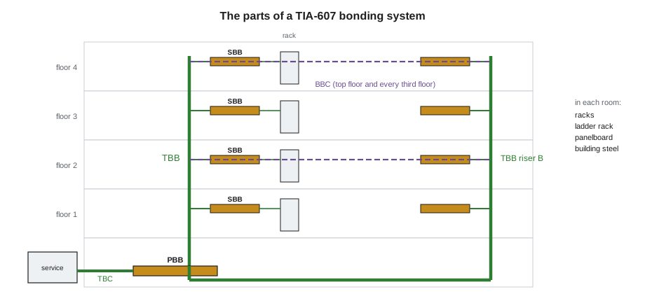
The parts of the system
The standard names each part, and recent editions renamed several of them, so both the old and new names still appear on drawings:
- The primary bonding busbar, PBB, formerly the telecommunications main grounding busbar, TMGB. There is normally one per building, in the entrance facility or the main equipment room, close to the electrical service.
- The telecommunications bonding conductor, TBC, formerly the bonding conductor for telecommunications, BCT. It connects the PBB to the electrical service's grounding, at the service equipment or the bonding point the electrician provides.
- Secondary bonding busbars, SBB, formerly telecommunications grounding busbars, TGB. There is one in each telecommunications room and equipment room other than the room with the PBB.
- The telecommunications bonding backbone, TBB, a conductor that runs from the PBB through the building to each SBB.
- The backbone bonding conductor, BBC, formerly the grounding equalizer, which ties together two or more TBBs in a large building, at the top floor and at least every third floor.
- Equipment bonding conductors, which connect racks, cabinets, cable trays and equipment in each room to that room's busbar.
Busbars
Busbars are flat bars of bare or tin-plated copper, mounted on insulated standoffs so they do not contact the wall, and drilled for two-hole compression lugs. The standard sets minimum sizes: a PBB at least 1/4 in thick and 4 in wide, an SBB at least 1/4 in thick and 2 in wide, each long enough for the connections it serves plus room for growth. They are mounted where they are accessible, usually on the backboard or wall of the room, close to the panelboard that serves the room and to the cable entrance. Tin-plating reduces corrosion and the need for antioxidant, and many specifications require it.
A busbar is planned like a patch panel: count the connections it will need now and in future, and pick a length with enough hole pairs. At the PBB those connections include the TBC to the service, each TBB, the protectors, the cable shields entering the building, the entrance room's racks and trays, the building steel and the panelboard serving the room. At each SBB they include the TBB, any BBC, the racks, cabinets and ladder racks, the panelboard, the building steel and spares.
# Busbar planning: two-hole lug positions needed now and with spares, and the bar length that holds them
import math
PITCH = 1.0             # in per two-hole lug position, including spacing
rooms = {  # room: list of connections now
    "Entrance room (PBB)": ["TBC to service", "TBB riser A", "TBB riser B", "protectors", "OSP shields",
                            "rack 1", "rack 2", "ladder rack", "panel LP-B", "building steel"],
    "TR 7 (SBB)": ["TBB riser A", "BBC to riser B", "rack 1", "rack 2", "ladder rack", "panel LP-7", "building steel"],
}
for room, conns in rooms.items():
    now = len(conns)
    need = math.ceil(now * 1.5)               # half again for growth
    length = need * PITCH
print(f"{room:22s} {now:2d} connections now, {need:2d} positions with spares, bar about {length:.0f} in long")Entrance room (PBB) 10 connections now, 15 positions with spares, bar about 15 in long TR 7 (SBB) 7 connections now, 11 positions with spares, bar about 11 in long
Sizing the backbone
The TBB must be large enough to keep its impedance low over the distance it runs, which means it grows with length. The minimum for any bonding conductor in the system is 6 AWG copper. The TBB is sized by its length, and recent editions of the standard express the rule as about 2 kcmil of conductor per linear foot of length, with a maximum of 750 kcmil. Earlier editions and many specifications use a table of lengths and sizes; a typical version is shown below. The TBC from the PBB to the service must be at least as large as the largest TBB, and a BBC at least as large as the TBBs it connects.
| TBB length | Minimum size |
|---|---|
| less than 13 ft | 6 AWG |
| 14 to 20 ft | 4 AWG |
| 21 to 26 ft | 3 AWG |
| 27 to 33 ft | 2 AWG |
| 34 to 41 ft | 1 AWG |
| 42 to 52 ft | 1/0 AWG |
| 53 to 66 ft | 2/0 AWG |
| greater than 66 ft | 3/0 AWG |
# TBB size by length: kcmil-per-foot rule of recent editions, rounded up to a standard size
SIZES = [("6 AWG", 26.24), ("4 AWG", 41.74), ("3 AWG", 52.62), ("2 AWG", 66.36), ("1 AWG", 83.69),
         ("1/0", 105.6), ("2/0", 133.1), ("3/0", 167.8), ("4/0", 211.6), ("250 kcmil", 250), ("300 kcmil", 300),
         ("350 kcmil", 350), ("500 kcmil", 500), ("750 kcmil", 750)]
def tbb_size(length_ft):
    need = min(2 * length_ft, 750)
    for name, kcmil in SIZES:
        if kcmil >= need:
            return name, need
    return "750 kcmil", need
runs = [("TR 2", 30), ("TR 7", 88), ("TR 12", 150)]   # length from the PBB along the route, ft
for room, length in runs:
    ft = length
    name, need = tbb_size(ft)
print(f"{room:6s} {length:5} ft -> needs {need:5.0f} kcmil -> {name}")TR 2 30 ft -> needs 60 kcmil -> 2 AWG TR 7 88 ft -> needs 176 kcmil -> 4/0 TR 12 150 ft -> needs 300 kcmil -> 300 kcmil
The two methods give different answers for long runs, which is why the specification must say which applies. Kellerman's specification names TIA-607-D, so Sanjay sizes each TBB by the kcmil rule and checks it against the table, and uses one TBB size for the whole riser, sized for the farthest room, so the conductor can run continuously past each floor with taps to each SBB. A continuous TBB with listed tap connectors at each floor is the usual design; splicing is allowed only with listed connectors or exothermic welds and kept to a minimum.
Routing and installing the backbone
- The TBB runs as directly as practicable from the PBB to the SBBs, usually in the riser beside the backbone cabling, supported every meter or so and protected from damage.
- It is insulated, with a green jacket or green marking, and continuous, without sharp bends; bends are kept to a radius of at least 8 in and an angle of at least 90 degrees where possible.
- It is not run in ferrous metal conduit unless the conduit is bonded to the conductor at both ends, because a steel conduit around a single conductor acts as a choke and raises the conductor's impedance to surges.
- Metallic cable shields, water pipes and building steel are not substitutes for the TBB. Building steel is bonded to the busbars where it is accessible, as an additional path, but the TBB is a separate conductor.
- Every conductor and busbar is labeled as TIA-606 and the specification require. The usual warning label reads in effect: if this connector or cable is loose or must be removed, call the building telecommunications manager.
Bonding inside the room
In each telecommunications room, the SBB is the hub. Each rack or cabinet is bonded to it with a rack bonding conductor, usually 6 AWG, either individually or through a rack bonding busbar running along the top of a row. Equipment in the rack bonds to the rack through its mounting with paint-piercing hardware or through its own bonding conductor, and shielded patch panels bond through the rack. Ladder racks and cable trays are bonded with jumpers across every joint that is not mechanically continuous, and to the SBB. The panelboard serving the room is bonded to the SBB, so that the power ground and the telecom bonding in that room are tied together at a known point.
The connections in the room use the same practices as lesson 10: listed two-hole compression lugs on busbars, paint removed under every lug, antioxidant where required and no screws through paint. Conductors are kept short, and taps to the busbar are made with listed tap connectors rather than by looping the TBB through the busbar.
Testing the bonding system
Bonding connections are inspected visually and tested electrically. The visual check covers lug type and crimp, tightness, removal of paint, conductor size and labels. The electrical check is usually a two-point bonding test, measuring the resistance between each busbar and the PBB, or between equipment and its busbar, with a low-resistance ohmmeter. TIA-607 leaves the limits to the design; many specifications require no more than 100 milliohms between any point in the bonding system and the PBB, and much less between a rack and its own busbar. A high reading points to a loose or corroded connection or a missing bond.
Testing is done before the system is energized and again at closeout. The results go in the closeout records with the conductor sizes, routes and busbar locations, and they become the baseline for the owner's maintenance: a bonding system that measured 25 milliohms at handover and 400 milliohms five years later has a failing connection somewhere.
Large buildings and data centers
Buildings with several risers have a TBB in each, tied together by BBCs at the top floor and at least every third floor in between, so that the backbones stay at the same potential. Data centers go further, with a mesh-common bonding network of conductors under the raised floor or overhead, bonded to every rack, and supplementary bonding grids. Those designs are covered by TIA-942 and the data center specification, and they follow the same principles: everything bonded, conductors short and large, and one connection to the building's grounding.
Worked problem
Sizing Kellerman's riser
Kellerman's PBB is in the basement entrance room. The riser runs up the north shaft to TR 12, the farthest room, 150 ft along the route from the PBB. The specification names TIA-607-D. What size should the TBB be, and the TBC?
Show solution
- At 2 kcmil per foot, the TBB needs about 300 kcmil, so the next standard size is 300 kcmil.
- The older table would give 3/0 AWG for any run over 66 ft; the specification's edition governs, so 300 kcmil.
- The TBC to the service must be at least as large as the largest TBB: 300 kcmil.
- Each SBB is tapped off the continuous TBB with a listed tap connector and a 6 AWG or larger tap.
Answer: The specification's edition decides. Sanjay notes the size on the riser diagram, and Ravi, who will land the TBC at the service, confirms that his lugs at the service accept it.
Coordinating the bonding system with the electrician
The TIA-607 system meets the electrical system at three kinds of point, and each needs agreement on the drawings. At the service, the TBC lands where the electrical engineer has designated, and the electrician usually makes that connection. In each telecommunications room, the panelboard serving the room is bonded to the SBB, a conductor the electrician may provide. And at building steel, the bond is often an exothermic weld made by a specialist. Kellerman's interface list from lesson 1 gives each of these an owner, and Maya checks every one of them on the pre-inspection walk in lesson 12.
Common mistakes
MistakeMixing old and new names on the same drawing without a legend.
InsteadUse PBB, SBB and TBC, and note the former names TMGB, TGB and BCT.
MistakeSizing the TBB for the nearest room.
InsteadSize it for the farthest room and run it continuously, with taps to each SBB.
MistakeRunning the TBB in steel conduit without bonding the conduit.
InsteadBond ferrous conduit to the conductor at both ends, or avoid it.
MistakeUsing a water pipe or building steel instead of a TBB.
InsteadBond them as extra paths; the TBB is a separate conductor.
MistakeSkipping the bonding test.
InsteadMeasure busbars and equipment against the specification's limit and record the baseline.
Summary and key terms
- TIA-607 sets out a telecommunications bonding system from the electrical service to every telecommunications room.
- The PBB is bonded to the service by the TBC; the TBB runs to an SBB in each room; BBCs tie multiple TBBs together.
- Busbars are tin-plated or bare copper on insulated standoffs, drilled for two-hole lugs, with room for growth.
- The TBB grows with length: about 2 kcmil per foot in recent editions, or a length table in older ones; the minimum is 6 AWG.
- Racks, trays, panels and steel in each room bond to the SBB with short conductors and listed connections.
- Two-point resistance tests confirm the connections; many specifications set 100 milliohms or less to the PBB.
- PBB
- Primary bonding busbar, the main busbar near the electrical service.
- SBB
- Secondary bonding busbar, the busbar in each telecommunications room.
- TBB
- Telecommunications bonding backbone, the conductor from the PBB to each SBB.
- TBC
- Telecommunications bonding conductor, from the PBB to the electrical service grounding.
- BBC
- Backbone bonding conductor, tying multiple TBBs together.
- Two-point bonding test
- A low-resistance measurement between two points of the bonding system.
Practice problems
Work each problem on paper first, then reveal the answer to check.
What was the PBB called in older editions?
Show answer
The telecommunications main grounding busbar, TMGB.
What is the minimum size of any bonding conductor in the TIA-607 system?
Show answer
6 AWG copper.
Where are BBCs installed in a building with two risers?
Show answer
At the top floor and at least every third floor.
What does a rising two-point resistance over the years indicate?
Show answer
A loose or corroded connection.
Lesson quiz · 5 questions
Score 60% or more to complete this lesson.
Create a free account to save your progress, take quizzes and earn a certificate.