
LVT-130 · Lesson 7 of 12 · 19 min
Terminating patch panels and racks
At the room end, every horizontal cable terminates on a patch panel port. The panel is where the cabling system meets the network: the switches plug into it, the owner's IT staff patch from it, and the tester connects to it. Room 6A has eight 48-port panels, A to H, for the 348 horizontal cables, plus panels for the backbone and building systems in rack 3. This lesson covers the two families of patch panel, their termination, the layout of ports and labels, and the finishing of the racks.
Modular and punch-down panels
Patch panels for Category 6A come in two families. A punch-down panel has a printed circuit board behind its front ports, with insulation displacement blocks on the rear, often in the 110 style, arranged in groups of eight positions per port. Each cable is dressed to its block, its pairs laid into the slots in the color order printed on the block, and each conductor seated and trimmed with an impact punch-down tool. A modular panel is an empty frame into which individual jacks snap; each cable is terminated on a jack exactly as in lesson 6, and the jack is then clipped into its position in the frame.
Each family has its supporters. Punch-down panels are compact and fast for an experienced installer, and every port is fixed in its place. Modular panels let the installer terminate jacks on a bench or at a comfortable height, replace a single damaged port without disturbing its neighbors, and mix jack types or colors in one frame. Brightwater's specification calls for modular panels using the same tool-less jacks as the outlets, which also means one termination method for the whole floor.
Panels may be flat or angled. An angled panel turns the ports so that cords leave toward the vertical managers on each side, removing the need for horizontal managers between panels. The rack elevation from LVT-120 originally showed angled panels; Sanjay's response to Maya's request for information confirmed flat panels with horizontal managers, which suit the interconnect layout Brightwater chose.
Punch-down technique
Even on a job with modular panels, punch-down terminations appear at the zone box connectors, at backbone copper blocks and in many existing rooms. The technique is simple but unforgiving. Each pair is brought to its position in the block with its twist intact as close to the slots as possible. Each conductor is laid into its slot in the order of the color code, then seated with an impact tool fitted with the correct blade, the cutting edge facing the waste side so the excess is trimmed. The impact tool's force setting should match the block; too low a setting leaves conductors unseated, too high can damage the slot.
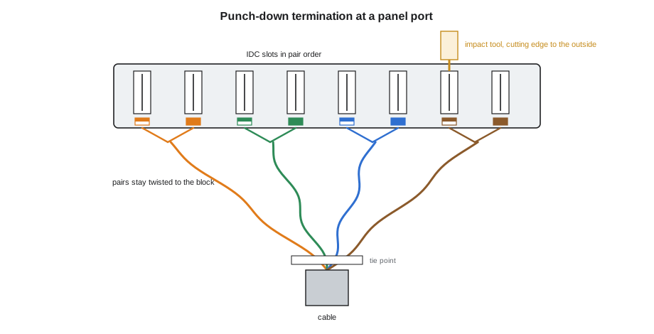
The color code printed on panel blocks is often a combined label showing both T568A and T568B, with each wiring scheme in its own row. As the example in lesson 6 showed, an installer following the wrong row will wire a whole panel to the wrong scheme. On Cobalt Line jobs, the unused row is covered with a strip of label tape before work starts.
Port layout and identifiers
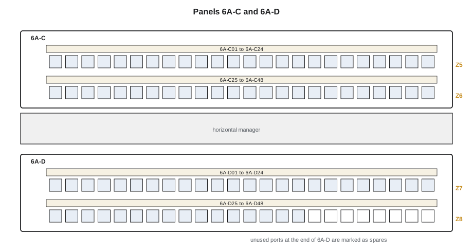
The order in which cables land on the panels is a design decision with long consequences. A logical port layout makes the room easy to manage: when a user at desk 6-C-07 reports a problem, the IT staff should be able to go to the right port without looking anything up. Cobalt Line's practice, and Sanjay's design for the sixth floor, assigns panel ports zone by zone and, within each zone, in the order of the outlets on the floor plan. Ports are filled in order with no gaps except deliberate spare ports at the end of each panel.
The identifiers follow the owner's TIA-606 scheme: room 6A, panel letter, port number. Panel A holds zones Z1 and Z2, panel B zones Z3 and Z4, and so on, with the offices, meeting rooms and ceiling devices on panels E to H. The same identifier appears on the panel port, on the outlet faceplate, in the test results and in the records, and lesson 12 uses that to check that every test belongs to a real link. The code below builds the port map from Sanjay's outlet schedule and checks it for duplicates and overfilled panels.
# Build the panel port map for room 6A from the outlet schedule
import string
PORTS = 48
schedule = [("Z1", 24), ("Z2", 24), ("Z3", 24), ("Z4", 24), ("Z5", 24), ("Z6", 24),
            ("Z7", 24), ("Z8", 24), ("offices", 54), ("meeting", 40), ("reception", 12),
            ("ceiling", 38), ("displays", 8), ("building", 4)]
panel, port = 0, 1
links, first_last = [], {}
for group, count in schedule:
    ids = []
    for _ in range(count):
        if port > PORTS:
            panel, port = panel + 1, 1
        ids.append(f"6A-{string.ascii_uppercase[panel]}{port:02d}")
        port += 1
    links += ids
    first_last[group] = (ids[0], ids[-1])
assert len(links) == len(set(links)), "duplicate identifier"
for group, (a, b) in first_last.items():
    print(f"{group:9s} {a} to {b}")
print("total links:", len(links), " panels used:", panel + 1,
" spare ports on the last panel:", PORTS - (port - 1))Z1 6A-A01 to 6A-A24 Z2 6A-A25 to 6A-A48 Z3 6A-B01 to 6A-B24 Z4 6A-B25 to 6A-B48 Z5 6A-C01 to 6A-C24 Z6 6A-C25 to 6A-C48 Z7 6A-D01 to 6A-D24 Z8 6A-D25 to 6A-D48 offices 6A-E01 to 6A-F06 meeting 6A-F07 to 6A-F46 reception 6A-F47 to 6A-G10 ceiling 6A-G11 to 6A-G48 displays 6A-H01 to 6A-H08 building 6A-H09 to 6A-H12 total links: 348 panels used: 8 spare ports on the last panel: 36
The map confirms the 348 links on panels A to H, ending at 6A-H12, with 36 spare ports on panel H for growth. The desk zones fill panels A to D exactly, two zones per panel, which makes the room easy to read: anyone patching zone Z5 knows it is the top half of panel C. Maya prints the map, tapes a copy inside the door of room 6A and uses it to make the panel port labels.
Terminating at the rack
The rear of a panel is a cramped place to work, and good room termination starts with good dressing, as lesson 4 described. Maya's crews terminate one panel at a time. For a modular panel, the cables for the panel are dressed to the cable bar, cut to length so that each reaches its port with the stored extra length the specification calls for, and terminated on jacks at a working position below the panel. The jacks are then clipped into the frame in order, with each cable following its own path from the cable bar. For a punch-down panel, the panel is often hinged down or terminated before it is mounted, then lifted into place with the cables dressed behind it.
Each cable at the panel is labeled within about 12 in of its termination with the same identifier as its port, a requirement of the TIA-606 scheme that makes it possible to find a cable behind a panel during later work. The labels are wrap-around or self-laminating, applied before termination so they can be read without twisting the cable.
When each panel is complete, the crew checks it from the front and the rear: ports in order, labels matching the map, no conductors visible outside the jacks, cables dressed and supported, and the cable bar carrying the weight. Then, following the quality plan from lesson 1, the first ten links on the panel are tested before the next panel is started.
Labeling the panel and the rack
Panel labels identify the panel and each port. The panel itself is labeled with its identifier, 6A-A to 6A-H, and each port with its number or its full identifier, depending on the owner's standard. Brightwater's standard puts the full identifier on a printed strip above each row of ports, so a user reading a port does not need to work out the panel letter. Racks are labeled with their own identifiers, and the zone groups on the ladder rack and at the cable bar carry the range of identifiers they serve.
Port icons or colored inserts, where the specification calls for them, match the outlet jack colors: blue data, white for ceiling devices and yellow for building systems. Ports set aside as spares are labeled as spares rather than left blank, so that nobody mistakes them for faults.
Backbone and building systems panels
Rack 3 holds the backbone: the 24-strand singlemode fiber from the building's equipment room in a fiber enclosure, which the fiber crew installs and tests under LVT-210, and the 25-pair copper backbone terminated on a voice panel or a 110 block for the building's telephone and alarm circuits. The 25-pair cable is terminated pair by pair in the standard color order of tip and ring colors, with each pair's twist kept to the block. Its testing is usually a wiremap and continuity test on each pair rather than full certification, because it carries low-frequency circuits.
The four building systems outlets, for the landlord's controls and meters, are the last links in the port map, 6A-H09 to 6A-H12, marked with yellow icons and cross-connected to a small switch the landlord owns in rack 3. The lease lets the landlord's contractors patch only that switch and those four ports, never Brightwater's equipment. That separation, written into the lease, is the kind of detail the installation plan has to capture and the port map has to show.
Worked problem
Changing the port map mid-job
After panels A and B are terminated, Brightwater moves two pods of desks: zone Z4's pod of 12 becomes a pod of 16, and zone Z8's shrinks to 8. What happens to the port map, and how should Maya handle it?
Show solution
- Zone Z4 needs four more ports. Panel B, which holds Z3 and Z4 at 24 each, is full.
- Rather than renumber every later port, the four new Z4 links take spare ports at the end of the plan, on panel H, and are recorded as part of Z4.
- Zone Z8's eight unused ports on panel D are labeled as spares.
- The map, the outlet drawings and the records are updated before any of the new cables are pulled, so the labels printed for the pull are correct.
Answer: Additions go to spare ports at the end of the plan instead of renumbering, and every record is updated before the pull.
Panels for shielded systems
Shielded cabling, which Cobalt Line installs at St. Brendan's imaging suite and in some industrial plants, uses shielded panels and jacks. Each jack has a metal body or a shield contact that the cable's foil and drain wire connect to, and the panel bonds every jack to its frame. The panel frame is then bonded to the rack, and the rack to the room's bonding busbar, so that the shield has a continuous, low-impedance path to the building's bonding system at the room end. A shielded system that is not bonded behaves worse than an unshielded one, because the shield can pick up noise and carry it along the link.
The termination steps add to those for unshielded jacks: the foil is folded back as the instructions describe, the drain wire is wrapped and clamped, and the shield clamp is closed over the jacket so it makes contact all around. Certification testers check shield continuity as part of the wiremap on shielded links, and a missing shield connection is reported as a failure. LVT-330 covers the bonding design and its testing; at the panel, the installer's task is to make every shield connection exactly as the manufacturer's instructions show.
Mixing shielded and unshielded components is not allowed. A shielded jack on unshielded cable, or the reverse, leaves the system neither one thing nor the other, and voids most warranties. The approved product list for each job makes the choice explicit, and the panels delivered are checked against it.
Common mistakes
MistakeFollowing the wrong row of a combined A/B color label.
InsteadCover the unused row before work starts.
MistakeFilling ports in whatever order cables arrive.
InsteadFollow the port map, zone by zone in floor plan order.
MistakeRenumbering every later port when a change is made.
InsteadUse spare ports and update the records.
MistakeLeaving spare ports unlabeled.
InsteadLabel spares as spares.
MistakeTerminating a whole panel before testing any of it.
InsteadTest the first ten links of each panel first.
Summary and key terms
- Patch panels are punch-down, with IDC blocks on the rear, or modular, with snap-in jacks.
- Punch-down terminations keep the twist to the block and use an impact tool set for the block.
- Combined A/B color labels cause scheme errors unless the unused row is covered.
- Ports are assigned zone by zone in floor plan order, with spares at the end of each panel.
- Identifiers match across panel, outlet, test results and records; cables are labeled near each termination.
- Panels are checked front and rear, and the first ten links are tested before the next panel.
- Backbone panels and the landlord's building systems ports are kept separate from the tenant's patching.
- Punch-down panel
- A patch panel with fixed IDC blocks on the rear for terminating each cable.
- Modular panel
- A patch panel frame that holds individual snap-in jacks.
- 110 block
- A common style of IDC termination block used on panels and for voice cabling.
- Impact tool
- A punch-down tool that seats and trims a conductor in an IDC slot.
- Port map
- The list of which link lands on which panel port.
- Spare port
- A port left for future use and labeled as such.
Practice problems
Work each problem on paper first, then reveal the answer to check.
How many 48-port panels are needed for 348 links, and how many spare ports remain?
Show answer
Eight panels with 36 spare ports.
Why is a cable labeled within about 12 in of its panel port as well as on the port?
Show answer
So it can be found behind the panel during later work.
What is the advantage of a modular panel when one port is damaged?
Show answer
A single jack can be replaced without disturbing its neighbors.
Why are the landlord's building systems ports kept separate and marked?
Show answer
So the landlord's contractors patch only their own ports and switch, never Brightwater's equipment.
Lesson quiz · 5 questions
Score 60% or more to complete this lesson.
Create a free account to save your progress, take quizzes and earn a certificate.