
LVT-130 · Lesson 10 of 12 · 20 min
Certification testing of permanent links and channels
Certification is the test that turns an installation into a deliverable. Every one of the sixth floor's 348 links must be tested with a certification tester against the Category 6A permanent link limits of TIA-568.2, and every result must be saved, reviewed and submitted to the manufacturer for the 25-year system warranty and to Brightwater as part of the records. A link that has not been certified, as far as the owner and the manufacturer are concerned, has not been installed. This lesson covers the tester, its setup, the test configurations, the parameters it measures and how to read its verdicts.
The certification tester
A certification tester is a pair of handheld units, a main unit and a smart remote, each with interchangeable adapters. The two units take turns sending and measuring, so that every parameter is measured from both ends of the link. The tester sweeps a range of frequencies, up to 500 MHz for Category 6A, and compares each measured value at each frequency with the limit line in the selected standard. A complete Category 6A autotest takes well under a minute per link with current testers.
Testers are themselves tested. TIA-1152-A sets accuracy levels for field testers: Level IIe for Category 5e, Level III for Category 6, Level IIIe for Category 6A and Level 2G for Category 8. A tester used for Category 6A certification must meet at least Level IIIe, and most current testers, such as the Fluke Networks DSX series or the Viavi Certifier series, meet the highest level and test to 2,000 MHz. Every tester must also be within its calibration period, usually one year, with a calibration certificate that the submittals include. Results from an out-of-calibration tester are not accepted.
Setting up the tester
Most failed test campaigns go wrong in the first five minutes of each day, at setup. Before the first test on the sixth floor, Maya's routine is the same every morning.
- Check the battery and that the main and remote units have the same firmware and limit database versions.
- Fit the permanent link adapters to both units, and check the adapters' plug ends and cords for damage.
- Set the reference: connect the two units together as the manufacturer describes and run the set-reference routine, which removes the adapters' own effects from later results. Repeat it whenever the adapters are changed, and at least daily.
- Select the test limit: TIA Category 6A Permanent Link, or the specific configuration for links that differ, such as an MPTL.
- Select the cable type, so the tester uses the correct NVP for length.
- Set the project, the operator name and the identifier sequence, so that each saved result gets the right identifier automatically.
The identifier sequence matters as much as the limit. Testers can step through a list of identifiers, 6A-A01, 6A-A02 and so on, saving each result under the next one. If the list is loaded and the crew tests in order, each saved result carries the right identifier without anyone typing. If the crew tests out of order or skips a link, the results and the identifiers drift apart. Lesson 12 shows how Maya cross-checks them before submitting.
Permanent link and channel tests
The permanent link test measures the installed cable and its two end connections, the panel jack and the outlet jack, and excludes the cords that will later be added. To do that, the tester uses permanent link adapters: short, high-quality test cords with plugs designed and characterized so that the tester can remove their effect, leaving the measurement of the link alone. The plug at the end of each adapter mates with the link's jack, and the connection between them is included in the measurement, as it should be, because the jack is part of the link.
The channel test measures everything between the two pieces of network equipment: the equipment cord, the panel, the horizontal cable, any consolidation point, the outlet and the work area cord. The tester uses channel adapters, which accept the plugs of the actual cords; the final connections at the equipment are not part of the channel, so the adapter's jack is excluded. Channel limits are slightly looser than permanent link limits, because the channel includes more cable and more connections.
Permanent link testing is the norm for new installations, because cords change and the permanent link does not. Certifying a channel certifies particular cords, and when those cords are replaced, the result no longer describes the system. Brightwater's specification calls for permanent link testing of every link and a sample of 5 percent of channels with the project's cords in place, which is common in specifications that include the cords in the warranty.
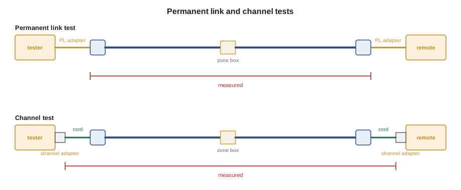
Links through a consolidation point, like the desk links through the sixth floor's zone boxes, are tested as permanent links that include the consolidation point: the tester's main unit at the panel, the remote at the desk outlet, and the zone box connectors in between. The MPTLs for the cameras use a different setup: a permanent link adapter at the panel, and at the camera end an adapter that accepts the link's plug, often a channel adapter or a dedicated MPTL adapter, as the tester maker's MPTL procedure describes. Dev's review in LVT-120 asked for that adapter to be named in the test plan, and it is.
What the tester measures
A Category 6A autotest measures the parameters that TIA-568.2 sets limits for, at each end of the link, and summarizes each as a margin: how far the worst measured value is from its limit.
| Parameter | What it measures | Typical cause of a failure |
|---|---|---|
| Wiremap | Each conductor reaches the right far-end contact | Termination errors, damage |
| Length | Electrical length of each pair | Route longer than planned, wrong NVP |
| Insertion loss | Signal lost along the link | Too long, warm ceiling, damaged cable |
| NEXT and PSNEXT | Crosstalk from one pair into others at the same end | Untwist, poor termination, wrong components |
| ACRF and PSACRF | Far-end crosstalk relative to the received signal | Mismatched components, damaged cable |
| Return loss | Signal reflected back by impedance changes | Kinks, tight ties, bad terminations, mixed cables |
| Propagation delay | Time for a signal to travel the link | Excess length |
| Delay skew | Spread in delay between the four pairs | Mixed cable types, damaged pairs |
| DC resistance and unbalance | Resistance of each conductor and difference within a pair | Poor contact, important for PoE |
Insertion loss and NEXT are the two that installers think about most. Insertion loss rises with length and frequency, so a long link has less margin than a short one. NEXT, which is measured close to the tester, depends mostly on the terminations near each end. That gives a useful pattern: long links tend to fail insertion loss, short links tend to fail NEXT, because on a short link the far-end termination is close enough to add its crosstalk to the near-end measurement. Return loss can fail at any length, and its graph usually shows where along the link the problem is, which lesson 11 uses.
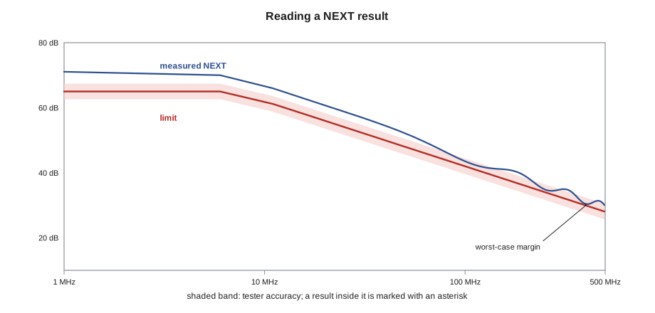
For each parameter the tester reports a margin in decibels. A positive margin means the link performs better than the limit by that amount; a negative margin means it fails. The tester also reports the frequency where the margin is smallest, the worst case, and for NEXT, which end it occurred at.
PASS, FAIL and the asterisk
Every measurement has some uncertainty, set by the tester's accuracy level. When a result is closer to the limit than the tester's accuracy, the tester marks it with an asterisk: PASS* means the measured value passed, but by less than the tester can be sure of; FAIL* means it failed, by less than the tester can be sure of. The overall result for the link is the worst of its parameters. Most specifications and warranty programs treat PASS* as a pass and FAIL* as a fail, but some project specifications reject PASS* results or require them to be reported separately, so the specification has to be checked. Brightwater's accepts PASS* but requires a list of them, which Maya prepares.
The code below shows the logic on three links from panel B and panel F, using illustrative limit lines with the general shape of the real ones and an illustrative accuracy band. The tester holds the real limits; the point here is how the margin and the verdict are worked out.
import math
FREQS = [1, 10, 100, 250, 400, 500]                                   # MHz
def il_limit(f):   return 1.65 * math.sqrt(f) + 0.01 * f               # illustrative limit line, dB
def next_limit(f): return min(65.0, 42.0 - 20 * math.log10(f / 100))   # illustrative limit line, dB
ACCURACY = 0.6     # a result closer to the limit than this is marked with an asterisk

def verdict(margin):
    if margin >= ACCURACY:
        return "PASS"
    if margin >= 0:
        return "PASS*"
    return "FAIL*" if margin > -ACCURACY else "FAIL"

# measured insertion loss as a fraction of the limit, and NEXT above the limit at each frequency
links = {
    "6A-B37": (0.62, [8.0, 7.0, 6.5, 5.2, 5.8, 4.9]),
    "6A-B48": (0.70, [3.0, 2.1, 1.5, 0.9, 0.4, 0.7]),
    "6A-F12": (0.27, [5.0, 3.0, 1.2, -0.3, -1.4, -0.9]),
}
for link, (frac, headroom) in links.items():
    il_margin = il_limit(500) * (1 - frac)      # margin at the top frequency
    k = min(range(len(FREQS)), key=lambda i: headroom[i])
    next_margin = headroom[k]
    worst = min(il_margin, next_margin)
    print(f"{link}: IL margin {il_margin:4.1f} dB at 500 MHz, worst NEXT margin {next_margin:4.1f} dB "
f"at {FREQS[k]} MHz -> {verdict(worst)}")6A-B37: IL margin 15.9 dB at 500 MHz, worst NEXT margin 4.9 dB at 500 MHz -> PASS 6A-B48: IL margin 12.6 dB at 500 MHz, worst NEXT margin 0.4 dB at 400 MHz -> PASS* 6A-F12: IL margin 30.6 dB at 500 MHz, worst NEXT margin -1.4 dB at 400 MHz -> FAIL
Link 6A-B37, a long desk link in zone Z4, passes comfortably. Link 6A-B48, the longest on the floor at 220 ft, has plenty of insertion loss margin but only 0.4 dB of NEXT margin at 400 MHz, within the accuracy band, so it is a PASS*. Link 6A-F12, a short meeting room link of about 79 ft, fails NEXT around 250 to 500 MHz even though its insertion loss is excellent: the classic short-link pattern, and a sign of a termination problem at one end. Lesson 11 follows Maya as she finds it.
Saving and reviewing results
Every test is saved, pass or fail, under its identifier. Failed links are fixed and retested, and the passing result is saved under the same identifier, replacing or superseding the failure according to the tester software's rules. At the end of each day, Maya downloads the tester into the manufacturer's management software, where Dev reviews the day's results: any failures not yet fixed, any PASS* results, any links with suspicious lengths, and any identifiers missing or duplicated.
The final submission is the native test file from the tester's software, not a spreadsheet or a printed summary, because the manufacturer's warranty team checks the raw data: the limit used, the adapter type, the tester's calibration date and the full graphs. A submission with the wrong limit selected, for example Category 6 instead of Category 6A, or channel instead of permanent link, is rejected and the links must be retested.
Worked problem
Choosing the right limit for an MPTL
The six camera links end in field-terminated plugs. Renée starts testing them with the standard permanent link setup, with a permanent link adapter on the remote, and finds that the remote's adapter has a plug, not a jack. What should the setup be?
Show solution
- An MPTL ends in a plug, so the remote needs an adapter that accepts a plug: a channel adapter or the tester maker's MPTL adapter.
- The main unit at the panel keeps its permanent link adapter, because the panel end is a jack.
- The limit is the TIA Category 6A MPTL limit, so that the plug connection at the camera end is included in the measured link.
- The test plan names the adapters and the limit, so Renée sets up the tester as listed and retests the six links.
Answer: Use a permanent link adapter at the panel, a plug-accepting adapter at the device end and the MPTL limit.
Common mistakes
MistakeStarting tests without setting the reference.
InsteadSet the reference daily and whenever adapters change.
MistakeTesting with a tester whose calibration has expired.
InsteadCheck the calibration date before the job; results are rejected otherwise.
MistakeSelecting the channel limit with permanent link adapters.
InsteadMatch the limit to the configuration and adapters.
MistakeTreating PASS* as a pass on every project.
InsteadCheck how the specification and warranty treat marginal results.
MistakeSubmitting a spreadsheet of results.
InsteadSubmit the native test files from the tester software.
Summary and key terms
- Certification measures every TIA-568.2 parameter across the category's frequency range from both ends.
- Category 6A requires a tester of at least TIA-1152-A Level IIIe, within its calibration period.
- Daily setup includes adapters, reference, limit, cable type and the identifier sequence.
- Permanent link tests measure jack to jack; channel tests include the cords; MPTLs use a plug-accepting adapter at the device end.
- Long links tend to fail insertion loss, short links NEXT; return loss can fail anywhere.
- Margin is the distance from the limit; asterisks mark results within the tester's accuracy.
- Every result is saved under its identifier and submitted in the tester's native format.
- Certification tester
- A field tester that measures link performance against standard limits across the full frequency range.
- Permanent link adapter
- A characterized test cord whose effect the tester removes, so that only the link is measured.
- Channel adapter
- An adapter that accepts the plug of the channel's own cord.
- Set reference
- A routine that removes the adapters' effect before testing.
- Margin
- The difference between a measured value and its limit, positive when passing.
- PASS* / FAIL*
- Results within the tester's accuracy band of the limit.
- Insertion loss
- The loss of signal strength along a link.
Practice problems
Work each problem on paper first, then reveal the answer to check.
What accuracy level must a tester meet for Category 6A certification?
Show answer
At least TIA-1152-A Level IIIe.
A link shows NEXT margin of −0.3 dB with an accuracy band of 0.6 dB. What is the result?
Show answer
FAIL*.
Why are new installations normally tested as permanent links?
Show answer
Cords change over time; the permanent link does not.
A short link fails NEXT but has large insertion loss margin. Where should the search start?
Show answer
At the terminations at each end.
Lesson quiz · 5 questions
Score 60% or more to complete this lesson.
Create a free account to save your progress, take quizzes and earn a certificate.