
LVT-130 · Lesson 5 of 12 · 20 min
Preparing cable and maintaining twists
Terminations are where most certification failures are made. The cable between the panel and the outlet is a factory product, built to tight tolerances; the last few centimeters at each end are a field product, built by hand on a ladder or at a rack. At those ends, the installer removes the jacket, separates the pairs, untwists each one a little, and pushes the conductors into the connector. Every one of those steps disturbs the geometry that gives the cable its performance. This lesson covers the preparation of the cable end, before the conductors go into the jack, because a good termination is mostly a well-prepared cable.
Why the twists matter
Each pair in a Category cable is a balanced transmission line. The two conductors carry equal and opposite signals, and the twist keeps them close together and makes any noise they pick up nearly identical on both, so it cancels at the receiver. The four pairs have different twist rates so that no two pairs sit side by side along the cable for long, which limits the coupling between them, the crosstalk that LVT-120 introduced as NEXT and FEXT. Category 6A cables add a separator, often a plus-shaped spline, and careful spacing to push the pairs further apart.
Where the installer untwists a pair to terminate it, the two conductors separate and the pair loses its balance over that short length. Where the jacket is stripped back, the pairs lose the spacing the separator and jacket gave them. The near end of the link, within the first meter or so of the tester, is where crosstalk is most sensitive, so a sloppy termination shows up clearly as a NEXT failure at that end. Most of what installers learn about termination comes down to keeping these disturbances as short as possible.
The untwist limit
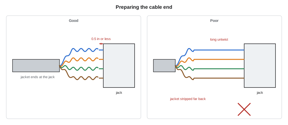
TIA-568.2 limits the length of untwisted conductor at a termination to no more than 0.5 in for Category 5e and higher. Most Category 6A connector manufacturers set a tighter limit in their instructions, or design the connector so that the pairs stay twisted almost to the contacts, and their instructions govern. The untwist is measured from the point where the pair's twist ends to the point where the conductor enters the contact.
A related limit applies to the jacket. The jacket should be removed only as far as necessary to terminate, so that the pairs keep their spacing right up to the back of the connector. Manufacturers give a strip length for each connector, often 1 to 2 in for a jack, which the installer trims back after the pairs are seated so that the jacket ends at or very close to the connector's cable entry.
Stripping the jacket
The jacket is removed with a stripping tool set for the cable, usually a rotary stripper with an adjustable blade or the connector manufacturer's own tool. The blade should score the jacket without cutting into the pairs; the jacket is then flexed until the score opens and slid off. A knife or a pair of side cutters can nick the conductor insulation, and a nick that does not show today can become a short or a high-resistance contact after years of temperature cycling.
Many Category 6A cables have a ripcord, a strong thread under the jacket that can be pulled back to slit the jacket without a blade. Using the ripcord for a short strip and trimming the loose jacket with snips protects the pairs. The separator spline is cut flush with the jacket, or at the length the connector instructions call for, with flush cutters. The spline is part of the cable's design, and some connectors use the stub of it to keep the pairs apart inside the jack's cable manager.
Shielded cables, which the sixth floor does not use but which Cobalt Line installs in some hospital and industrial jobs, need more care: the foil around each pair or around the core must be kept as intact as possible up to the connector, and the drain wire or braid must be terminated to the connector's shield contact exactly as the instructions describe. A shield that is broken back too far or bonded badly does more harm than good.
Handling the pairs
After stripping, the pairs are separated and laid out in the order the connector needs. The installer keeps each pair twisted, untwisting it only at the very end where it enters the connector's lacing cap or wire guide. Untwisting a pair and then trying to retwist it does not restore its performance; the factory twist is consistent along its length in a way hand twisting cannot match.
Conductors should not be straightened, stretched or kinked. On many jacks the conductors are laced into a cap that is then pressed onto the jack body, and the cap's guides set the positions; the installer's job is to lay each pair into its guide with the twist reaching as close to the guide as possible, then trim the excess conductor flush with the cap before pressing it on. Excess conductor left sticking out of a termination can touch a neighboring contact or act as a small antenna.
Pairs should also be kept in their place relative to each other. The orange and green pairs, which T568A and T568B swap, should not be crossed over the blue and brown pairs on the way to their contacts, because the crossing points couple the pairs. The connector's lacing cap usually makes the right layout obvious, which is one reason manufacturers design them that way.
The bend at the back of the connector
The cable's bend radius rule from lesson 3 applies right up to the connector. The most common place it is broken is behind a jack in a shallow outlet box, or behind a panel where the cable is forced to turn sharply to reach its port. A tight bend in the first few centimeters behind the termination crushes the pairs together and undoes all the care taken with the untwist. Angled patch panels and jacks with angled cable entries exist precisely to avoid this, and the deep outlet boxes from lesson 2 give the cable room to curve gently behind the faceplate.
Checking the preparation
Dev's crews check terminations with a simple routine, and early in a job they measure. A short steel rule held beside a finished termination shows the untwist on each pair and the gap between the end of the jacket and the connector. The code below shows how Maya records her checks on the first ten jacks of zone Z3, using the manufacturer's untwist limit and a limit on the jacket gap from the instruction sheet.
# First ten jacks in zone Z3: untwist on each pair and the jacket gap, in in
UNTWIST_MAX = 0.25     # manufacturer's limit (TIA-568.2 allows 0.5)
JACKET_GAP_MAX = 0.25  # jacket end to the back of the jack
checks = {
    "6A-B13": ((0.125, 0.15, 0.125, 0.15), 0.125), "6A-B14": ((0.15, 0.15, 0.2, 0.125), 0.15), "6A-B15": ((0.125, 0.2, 0.15, 0.15), 0.125),
    "6A-B16": ((0.15, 0.35, 0.3, 0.15), 0.2), "6A-B17": ((0.125, 0.15, 0.125, 0.15), 0.125), "6A-B18": ((0.2, 0.15, 0.15, 0.25), 0.15),
    "6A-B19": ((0.15, 0.15, 0.2, 0.125), 0.125), "6A-B20": ((0.125, 0.15, 0.125, 0.15), 0.5), "6A-B21": ((0.125, 0.2, 0.15, 0.15), 0.125),
    "6A-B22": ((0.15, 0.15, 0.2, 0.125), 0.15),
}
pairs = ("blue", "orange", "green", "brown")
for port, (untwist, gap) in checks.items():
    faults = [f"{p} {u}" for p, u in zip(pairs, untwist) if u > UNTWIST_MAX]
    if gap > JACKET_GAP_MAX:
        faults.append(f"jacket gap {gap}")
print(port, "ok" if not faults else "redo: " + ", ".join(faults))6A-B13 ok 6A-B14 ok 6A-B15 ok 6A-B16 redo: orange 0.35, green 0.3 6A-B17 ok 6A-B18 ok 6A-B19 ok 6A-B20 redo: jacket gap 0.5 6A-B21 ok 6A-B22 ok
Two of the ten need to be redone. Port 6A-B16 has its orange and green pairs untwisted too far, the classic result of fighting with the lacing cap. Port 6A-B20 has its pairs right but the jacket stripped well back from the jack, so the pairs are loose over that length. Neither would necessarily fail a test on a short link, but both reduce the margin, and on the long links in zone Z4 they could be the difference between PASS and FAIL. Maya re-terminates both and shows the apprentice who made them how to use the ripcord and trim the jacket after seating the cap.
The check also shows something reassuring: the other eight are well inside both limits. The manufacturer's lacing cap, used as designed, makes good terminations the normal result. Problems come from rushing, from a dull stripper, and from trying to terminate on a ladder in a position where the cable is pulled tight.
Working positions and cable ends at the outlet
At the outlet end, the cable usually arrives through the outlet box from the ceiling. Before stripping, the installer pulls out a working length, cuts off the pull label after copying the identifier to the permanent label, and leaves enough cable to terminate comfortably outside the box, typically 6 to 12 in. Once the jack is terminated, the extra length is fed back into the box in a gentle curve as the faceplate is fitted. Cutting the cable too short makes the termination awkward and forces a tight bend; leaving far too much means a coil crammed into the box.
In the room, the cables are terminated after dressing, with the length at each port set by the dressing. The working position is usually at the rear of the rack, with the panel either hinged or terminated on a bench and then mounted, according to the panel design.
Worked problem
A NEXT failure traced to preparation
On a previous job, a link at the Hartwell warehouse failed NEXT on the orange and green pair combination at the outlet end, by about 1 dB at around 400 MHz. The tester's diagnostic pointed to the outlet. What should Maya check first?
Show solution
- NEXT on the orange-green combination at one end points to the termination at that end, because those are the pairs moved most in either wiring scheme.
- She removes the faceplate and looks at the jack: the orange and green pairs are untwisted about 0.75 in and crossed over each other behind the cap.
- She cuts the cable back, re-strips with the ripcord and terminates a new jack with the twists carried to the cap.
- She retests: the link passes with about 4 dB of NEXT margin.
Answer: A termination with too much untwist and crossed pairs caused the failure; a clean re-termination fixed it.
Termination in awkward places
Some terminations cannot be done at a comfortable bench height. Ceiling outlets for access points, jacks in floor boxes and panels at the top of a rack all tempt the installer to work with the cable pulled tight or bent sharply into position. Maya's rule is to bring the work to a good position rather than the reverse: pull the cable end out to where it can be held without tension, terminate it there, and then feed it back with a gentle curve. For ceiling devices, that means terminating on a ladder at a height where the hands are below shoulder level, with the cable's service loop giving the slack to do so, and mounting the box afterwards.
Light and tools matter too. A headlamp, a magnifier for checking untwist on small connectors, sharp flush cutters and a clean stripper make better terminations than skill alone. Dull cutters leave ragged conductor ends that can bridge to a neighboring slot; a worn stripper blade nicks the pairs. Dev's crews replace stripper blades and cutters on a schedule rather than when they fail, and carry the manufacturer's termination instructions in the tool bag for every connector on the job.
Finally, the crew counts. On a 348-link floor, a five-second saving per termination means nothing; a single systematic error means hundreds of corrections. The first-ten rule from lesson 1 is applied to every new person on the floor as well as every new connector type.
Common mistakes
MistakeStripping the jacket back 3 in to make termination easier and leaving it that way.
InsteadStrip what is needed, then trim the jacket back to the connector after the pairs are seated.
MistakeUntwisting a pair fully and retwisting it by hand.
InsteadKeep the factory twist; untwist only at the very end.
MistakeCutting the spline off deep inside the jacket.
InsteadCut it flush or as the instructions say; it keeps the pairs apart.
MistakeUsing a knife or side cutters to strip the jacket.
InsteadUse the proper stripper or the ripcord to avoid nicking the pairs.
MistakeForcing a sharp bend behind the jack to fit the faceplate.
InsteadLeave a gentle curve and use a deep box or angled jack.
Summary and key terms
- Twisted pairs work by balance and by the separation the twists and spline give them; termination disturbs both.
- Untwist is limited to 0.5 in by TIA-568.2, or less where the manufacturer specifies.
- The jacket is removed only as far as needed and trimmed back close to the connector after seating.
- Strippers set for the cable, or the ripcord, avoid nicking the pairs.
- Pairs stay twisted, uncrossed and unstretched up to the lacing cap; excess conductor is trimmed flush.
- The bend radius applies right up to the back of the connector.
- Measuring the first terminations finds method problems early.
- Untwist
- The length of a pair that is no longer twisted at a termination.
- Separator (spline)
- A plastic core inside the cable that keeps the pairs apart.
- Ripcord
- A strong thread under the jacket used to slit it without a blade.
- Lacing cap
- A part of a jack that holds the conductors in position before termination.
- Balanced pair
- A pair of conductors carrying equal and opposite signals, so that noise cancels.
- Strip length
- The length of jacket removed to terminate a connector.
Practice problems
Work each problem on paper first, then reveal the answer to check.
A pair is untwisted 0.35 in at a jack whose instructions allow 0.25 in. Does it pass the TIA limit, and what should be done?
Show answer
It is within TIA's 0.5 in but over the manufacturer's limit; re-terminate it.
Why is the near end of a link the most sensitive to a poor termination?
Show answer
Crosstalk at the near end is strongest and is measured close to the tester, so local disturbances show clearly.
What tool should be used to remove the jacket?
Show answer
A stripper set for the cable or the ripcord, not a knife or side cutters.
Which pairs move between T568A and T568B, and why does that matter for termination?
Show answer
Orange and green; they are the pairs most often crossed or over-untwisted.
Lesson quiz · 5 questions
Score 60% or more to complete this lesson.
Create a free account to save your progress, take quizzes and earn a certificate.