
LVT-130 · Lesson 6 of 12 · 20 min
Terminating jacks and outlets (T568A and T568B)
An outlet jack is the most numerous connector on any cabling job. The sixth floor has 348 of them in the work areas and the ceiling, each terminated by hand, plus the 192 jacks at the eight zone boxes where the desk cables connect. This lesson covers the wiring schemes the jacks follow, how a typical Category 6A jack is terminated, and how the outlets and faceplates are finished. It builds on the cable preparation from lesson 5 and the connector types introduced in LVT-120.
Pin numbers and pairs
An eight-position modular jack, the familiar RJ45-style connector, has eight contacts numbered 1 to 8 from left to right when looking into the jack opening with the latch slot at the bottom, or into the end of a plug with the latch underneath and the contacts facing up. The four pairs of a cable occupy those eight contacts in a set pattern. Two patterns are standardized in TIA-568.2, called T568A and T568B. They differ only in which pair goes to contacts 1 and 2 and which to contacts 3 and 6: in T568A the green pair is on 1-2 and the orange pair on 3-6; in T568B they swap. The blue pair is on 4-5 and the brown pair on 7-8 in both.
| Contact | T568A | T568B | Pair position |
|---|---|---|---|
| 1 | white-green | white-orange | Pair on 1-2 |
| 2 | green | orange | Pair on 1-2 |
| 3 | white-orange | white-green | Pair on 3-6 |
| 4 | blue | blue | Pair on 4-5 |
| 5 | white-blue | white-blue | Pair on 4-5 |
| 6 | orange | green | Pair on 3-6 |
| 7 | white-brown | white-brown | Pair on 7-8 |
| 8 | brown | brown | Pair on 7-8 |
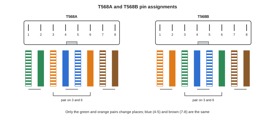
Either scheme works electrically, and a link terminated with the same scheme at both ends performs identically whichever is used. What matters is that both ends match and that the whole installation follows the scheme the specification calls for. TIA-568.2 lists T568A as the preferred scheme and T568B as an option. Many US commercial buildings were historically wired T568B, partly because it matched an older telephone wiring practice; Canadian government and many institutional specifications call for T568A. The sixth floor is T568A throughout, as Brightwater's specification states.
Mixing schemes is a common and avoidable fault. A link with T568A at one end and T568B at the other has the green and orange pairs crossed, which a wiremap test reports as a crossed pair, and which network equipment may or may not tolerate. More importantly, the cabling is no longer standard, and its records are wrong. The drawing detail that showed T568B colors, which Maya found in lesson 1, was corrected by Sanjay's response to her request for information.
Inside a Category 6A jack
Most modern jacks terminate with insulation displacement contacts, or IDCs: slotted metal contacts into which each insulated conductor is pressed. The slot's edges cut through the insulation and grip the copper, making a gas-tight connection without stripping each conductor. The jack's printed circuit board or contact design carries the signals from the IDCs to the eight front contacts, and in a Category 6A jack it also includes compensation, a carefully designed coupling that cancels the crosstalk created by the plug's own geometry. That compensation is tuned to the cable and plug being used, which is one reason a jack must be matched to its category and manufacturer's system.
Jacks come in two broad styles. Punch-down jacks have their IDCs exposed on top, and each conductor is laid into its slot and seated with a punch-down tool, which also trims the excess. Tool-less jacks hold the conductors in a lacing cap that is pressed onto the jack, seating all eight conductors at once, by hand or with a simple pliers-type tool. Many Category 6A product lines use tool-less designs because they keep the untwist short and the results consistent. The sixth floor's jacks are tool-less; the zone box connectors are a punch-down design.
Terminating a tool-less jack
The manufacturer's instruction sheet is the procedure, and the warranty depends on following it. A typical Category 6A tool-less termination at an outlet goes like this.
- Pull out the working length, transfer the identifier to the permanent label and remove the pull label.
- Strip the jacket to the length the instructions give, using the ripcord or a stripper set for the cable, and cut the spline as instructed.
- Fan the pairs out in the order the lacing cap shows for the chosen scheme, here T568A, keeping each pair twisted.
- Lay each conductor into its slot in the cap, carrying the twist as close to the slot as the cap allows, and pull it through.
- Trim the conductors flush with the face of the cap, using flush cutters, so that nothing protrudes.
- Press the cap onto the jack body squarely until it latches, with the tool if one is specified; check that every conductor is seated.
- Trim the jacket back if needed so it ends at the jack's cable entry, and fit any strain relief or cable tie point the jack provides, using the jack's own clip, not a cable tie on the cable.
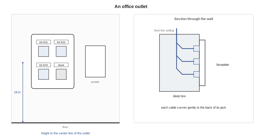
- Snap the jack into the faceplate or surface box in the position on the outlet drawing, keeping the cable in a gentle curve into the box.
Each step that goes wrong has a characteristic test result. A conductor not fully seated shows as an open or an intermittent contact. Two conductors swapped within the cap show as a reversed or crossed pair. Too much untwist shows as a NEXT failure or a small margin at that end. A cable pulled too tight behind the faceplate shows as a return loss problem close to the outlet.
Checking the scheme in the field
Before testing, a quick visual check at each end catches most scheme errors. Maya's crews look at the colors visible through the jack's window or at the back of the cap and compare them with the scheme. The code below shows the logic in a form Maya uses to train apprentices: given the colors seen on contacts 1 to 8, it reports which scheme the jack follows, or which contacts are wrong for the specified scheme.
T568A = ["white-green", "green", "white-orange", "blue",
         "white-blue", "orange", "white-brown", "brown"]
T568B = ["white-orange", "orange", "white-green", "blue",
         "white-blue", "green", "white-brown", "brown"]
SPECIFIED = "T568A"

def scheme(seen):
    if seen == T568A:
        return "T568A"
    if seen == T568B:
        return "T568B"
    return None

jacks = {
    "6A-C07": T568A[:],
    "6A-C08": T568B[:],
    "6A-C09": ["white-green", "green", "white-orange", "white-blue",
               "blue", "orange", "white-brown", "brown"],
}
ref = T568A if SPECIFIED == "T568A" else T568B
for port, seen in jacks.items():
    s = scheme(seen)
    if s == SPECIFIED:
        print(port, "ok,", s)
    elif s:
        print(port, "wrong scheme:", s, "instead of", SPECIFIED)
    else:
        bad = [i + 1 for i in range(8) if seen[i] != ref[i]]
print(port, "not a standard scheme; check contacts", bad)6A-C07 ok, T568A 6A-C08 wrong scheme: T568B instead of T568A 6A-C09 not a standard scheme; check contacts [4, 5]
Port 6A-C08 has been terminated T568B, probably by someone working from habit. Port 6A-C09 follows neither scheme: the blue pair's conductors are reversed on contacts 4 and 5, which a wiremap will report as a reversed pair. Both are caught before the faceplates are fitted, and both are quick to fix.
Faceplates, surface boxes and outlet labeling
Faceplates hold the jacks at the wall. On the sixth floor, desk outlets in the pods are mounted in the furniture's raceway from the zone boxes; office and meeting room outlets are in walls, at the height shown on the outlet drawing, beside the electrical receptacles. Each faceplate is labeled with the identifiers of its jacks, on the plate's label window or a printed label, in the format the owner's TIA-606 scheme requires. Blank inserts fill unused positions so no opening is left.
Access points, cameras and card readers are served from the ceiling. Their cables end either in a surface-mount box above the ceiling, with a short equipment cord to the device, or in a field-terminated plug that connects directly to the device, as lesson 8 describes. Sanjay's design uses surface boxes for the access points, so the device can be replaced without touching the horizontal cable, and field-terminated plugs for the cameras, which are mounted on the ceiling surface with no room for a box.
Jack colors are also part of the specification. Brightwater's standard is blue jacks for data, white for access points and other ceiling devices, and yellow for the building systems outlets the landlord has asked for. The colors make it easy to tell at a glance what a port is for, and they must match the panel port icons in the room.
Zone box connectors
The zone boxes on the sixth floor are consolidation points: the horizontal cable from room 6A ends in a connector in the box, and a short cable continues to the desk outlet. Each is a mated pair of connectors, one terminated on the cable from the room and one on the cable to the desk, so each desk link has a connection in the zone box in addition to the jacks at each end. These connectors are terminated with the same care as any jack, and the test configuration for links through a consolidation point is set up to include them, as lesson 10 explains.
Because consolidation points will be reworked when the furniture changes, the cables to the desks are labeled at the zone box end as well as at the outlet. The records for each zone box list which room cable connects to which desk cable, so that a future installer moving a desk can find the right connector without tracing.
Worked problem
A floor wired with both schemes
During the first round of verification tests on zone Z1, the tester reports crossed pairs on 1-2 and 3-6 for 11 of the 24 links. All 11 were terminated by one installer at the panel end on the same afternoon. What has happened, and how should it be corrected?
Show solution
- A crossed 1-2 and 3-6 result means one end is T568A and the other T568B.
- Because all 11 share one installer and one end, the likely cause is that the panel ports were punched to T568B by habit.
- Maya checks the panel's color label strip: it is a combined A/B label, and the installer followed the B row.
- The panel ports are re-terminated to T568A, the label strip is covered so only the A row shows, and the 11 links are retested.
Answer: One end had been wired to the other scheme; re-terminating the panel ports to T568A and fixing the cause on the label strip cleared every result.
Outlets in furniture and floor boxes
Many desk outlets on the sixth floor are not in walls but in the furniture's power and data raceway, fed from the zone boxes through flexible conduit or the furniture's own pathways. The jacks clip into openings in the raceway cover, often with an adapter frame supplied by the furniture maker. The furniture dealer and Cobalt Line agree in advance which openings take which jacks, so that the outlet identifiers on the drawing match the positions at the desks, and Maya checks a sample desk before the dealer installs the rest.
Floor boxes, used in the boardroom and training room where tables stand away from the walls, combine power and data in one box set into the floor. The data side holds jacks in a frame under a cover that closes over the cords. Floor boxes are cramped, and the cable has to make a tight turn from the floor conduit into the box, so Sanjay specified boxes deep enough for Category 6A and the crews leave just enough slack to terminate outside the box and fold the cable back gently.
In both places, the labels are harder to see, so Brightwater's standard adds the identifier to the inside of the cover as well as beside each jack. The records list the furniture or floor box position for each outlet, so that a later move can find it without lifting covers along a whole row.
Both also need protection while the floor is finished. Jacks in floor boxes are installed after the flooring crew is done, and furniture jacks are installed only when the furniture is in place; until then, the cable ends are coiled, bagged and labeled in the box, never left loose where a floor scrubber can catch them.
Common mistakes
MistakeTerminating one end T568A and the other T568B.
InsteadUse the specified scheme at both ends of every link.
MistakeAssuming T568B because it is common.
InsteadCheck the specification; T568A is preferred in TIA-568.2 and common in Canadian and institutional specifications.
MistakeLeaving conductor ends sticking out of the cap.
InsteadTrim flush before pressing the cap on.
MistakeLeaving open faceplate positions.
InsteadFit blank inserts in unused positions.
MistakeUsing a jack from another manufacturer to finish a job.
InsteadUse only components on the approved product list.
Summary and key terms
- Modular jacks have contacts 1 to 8; the four pairs occupy 1-2, 3-6, 4-5 and 7-8.
- T568A and T568B differ only in swapping the green and orange pairs; T568A is TIA's preferred scheme.
- Both ends of every link must use the specified scheme.
- Category 6A jacks use insulation displacement contacts and built-in compensation matched to their system.
- Tool-less jacks are terminated by lacing a cap and pressing it on, following the manufacturer's instructions exactly.
- Faceplates are labeled, unused positions are blanked, and jack colors follow the owner's standard.
- Consolidation point connectors add a connection to each desk link and are labeled at the zone box.
- T568A / T568B
- The two standard pair-to-contact assignments for eight-position modular jacks.
- Insulation displacement contact (IDC)
- A slotted contact that cuts through a conductor's insulation to make a connection.
- Compensation
- Designed coupling inside a jack that cancels crosstalk created by the plug.
- Tool-less jack
- A jack terminated by pressing a lacing cap onto the body, seating all conductors at once.
- Faceplate
- The wall plate that holds jacks at an outlet.
- Blank insert
- A cover that fills an unused faceplate position.
Practice problems
Work each problem on paper first, then reveal the answer to check.
In T568A, which conductor is on contact 1, and which on contact 6?
Show answer
White-green on contact 1 and orange on contact 6.
A link is T568B at the panel and T568A at the outlet. What will a wiremap test report?
Show answer
Crossed pairs between 1-2 and 3-6.
Which pairs are the same in both schemes?
Show answer
Blue on 4-5 and brown on 7-8.
Why are tool-less jacks common in Category 6A product lines?
Show answer
They keep untwist short and give consistent results.
Lesson quiz · 5 questions
Score 60% or more to complete this lesson.
Create a free account to save your progress, take quizzes and earn a certificate.