
LVT-130 · Lesson 11 of 12 · 19 min
Troubleshooting failures: NEXT, return loss and length
On a well-run job, most links pass the first time. On the sixth floor, after the first week of certification, 291 of the 300 links tested so far have passed, three are PASS*, and six have failed. Each failure is a small investigation. The tester says what failed and roughly where; the installer has to work out why, fix it, and make sure the same cause is not lurking in the links that passed. This lesson follows Maya through the failures, using the tester's diagnostic tools and the patterns that experienced technicians learn to recognize.
Start with the pattern, not the link
Before going to any one link, Maya sorts the failures. Six failures spread across six zones and six crews suggest six unrelated causes. Six failures in one zone, on one panel or by one crew suggest one cause repeated. She also looks at which parameter failed, at which end, and on which pairs, because the same failure on the same pair combination at the same end of several links points straight at a termination method.
| Link | Length | Failed parameter | Worst case | Where |
|---|---|---|---|---|
| 6A-F12 | 79 ft | NEXT | −1.4 dB at 400 MHz | Outlet end, pairs 3-6 and 1-2 |
| 6A-F19 | 85 ft | NEXT | −0.8 dB at 450 MHz | Outlet end, pairs 3-6 and 1-2 |
| 6A-F21 | 72 ft | NEXT | −1.1 dB at 380 MHz | Outlet end, pairs 3-6 and 1-2 |
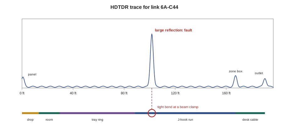
| 6A-C44 | 190 ft | Return loss | −1.9 dB at 210 MHz | About 102 ft from the panel |
| 6A-D09 | 200 ft | Wiremap | Open on pin 6 | Far end |
| 6A-G27 | 305 ft | Insertion loss and length | −0.6 dB at 500 MHz | Whole link |
Three of the failures are short meeting room links on panel F, all NEXT failures at the outlet end on the same pair combination. The other three are each different. The meeting room links were terminated by one apprentice on the same day, using the outlets in the meeting room walls, and that is where Maya starts.
Diagnosing NEXT: the crosstalk graph and HDTDX
Certification testers include a time-domain crosstalk analysis, called HDTDX on Fluke Networks testers and by similar names on others, which shows where along the link the crosstalk comes from. The display plots crosstalk against distance from the tester. A healthy link shows small bumps at each connection and low, even crosstalk along the cable. A bad termination shows a large peak at the distance of the connector. A long stretch of high crosstalk along the cable points to the cable itself: damaged, crushed or of the wrong category.
For the three meeting room links, the HDTDX trace shows a sharp peak at the outlet end on each. NEXT failures on the 3-6 and 1-2 pair combination, at one end, on short links, are almost always too much untwist or a disturbed pair layout at that end's connector. Maya removes one faceplate and finds what she expected: the apprentice had stripped the jacket back far from the jack and then untwisted the orange and green pairs to reach the lacing cap, leaving about 0.75 in of untwisted conductor. The meeting room walls had shallow boxes from an earlier fit-out, and the cables had been bent tightly behind the jacks as well.
The fix has two parts. All three jacks are re-terminated with fresh cable ends, and the links retested: all pass with 3 to 4 dB of NEXT margin. The cause is fixed too: Maya shows the apprentice the method again, asks the electrical contractor to replace the shallow boxes in the two meeting rooms not yet terminated, and has Renée check the next ten of the apprentice's terminations.
Diagnosing return loss: HDTDR and distance to fault
Return loss measures the signal reflected back to the tester by changes in impedance along the link. Every connection reflects a little, and the cable itself reflects a little everywhere, but a sharp change, such as a kink, a crush, a tight cable tie or a splice, reflects much more. The time-domain reflectometry view, HDTDR on Fluke Networks testers, shows the reflections plotted against distance, just as HDTDX shows crosstalk. A peak in the middle of a link, well away from either connector, is almost always physical damage to the cable at that point.
Link 6A-C44 fails return loss with a peak about 102 ft from the panel. The distance comes from the time of the reflection and the cable's NVP, as lesson 9 explained. The code below converts the reflection times the tester reports into distances and places each one on the link's route, using the route Maya recorded on the pull sheet.
# Place reflections on link 6A-C44 using the route from the pull sheet
c = 299_792_458
NVP = 0.68
route = [(0.0, "panel jack in room 6A"), (4.0, "ladder rack drop"), (9.0, "tray ring, south corridor"),
         (27.0, "J-hook run into zone Z6"), (51.0, "zone box Z6"), (58.0, "desk outlet")]
reflections_ns = [(2, 0.8), (304, 4.6), (500, 0.9), (568, 0.7)]   # (round-trip time, size)

def where(d):
    name = route[0][1]
    for start, part in route:
        if d >= start - 0.5:
            name = part
    return name

for t, size in reflections_ns:
    d = NVP * c * t * 1e-9 / 2 * 3.281
    flag = "  <-- large, check here" if size > 2 else ""
print(f"{d:5.1f} ft from the panel, size {size}: {where(d / 3.281)}{flag}")0.7 ft from the panel, size 0.8: panel jack in room 6A 101.7 ft from the panel, size 4.6: J-hook run into zone Z6 <-- large, check here 167.2 ft from the panel, size 0.9: zone box Z6 190.0 ft from the panel, size 0.7: desk outlet
The small reflections at the start, at the zone box and at the outlet are the connections, as expected. The large one is about 102 ft from the panel, in the J-hook run into zone Z6. Maya climbs up at that point and finds the bundle pulled tight around the edge of a beam clamp where a hook had been moved after the pull, with a hook-and-loop strap cinched hard right at the bend. She loosens the strap and re-hangs the hook to give the bundle a smooth curve. The retest shows the peak much reduced, but the return loss margin is only 0.3 dB, a PASS*. Because the cable was deformed, Dev decides to replace it; the new cable passes with about 4 dB of margin. Two other cables in the same strap show small peaks at the same spot, which explains why they passed with less margin than their neighbors, and they are replaced too.
Opens, shorts and the far end
Wiremap failures are the easiest to locate, because most testers report the distance to an open or a short as well as the pins involved. Link 6A-D09 shows an open on pin 6 at the far end, the full length of the cable away. The outlet jack's orange conductor, on contact 6 in T568A, is not seated in its slot: the lacing cap was pressed on at a slight angle, and one conductor slipped out of its guide. Re-terminating the jack fixes it.
An open part way along a cable, with no connector nearby, means a broken conductor, usually from a cable crushed or cut during other work. Shorts in the middle of a cable usually mean the insulation has been pierced, by a staple, a screw through a wall or a drill. Both mean replacing the cable. Opens or shorts at a connector are terminations to be redone.
Length and insertion loss failures
Link 6A-G27, a camera link, reports a length of 305 ft and fails insertion loss at the top of the frequency range. A long-link insertion loss failure has only three common causes: the link really is too long, the cable is warmer than the limit assumes, or the cable or connections have higher loss than they should. The length is the first thing to check, because the tester's length depends on its NVP setting. Renée had tested the cameras after the backbone, and the tester was still set to the backbone cable's NVP. Corrected, the length is about 292 ft, just inside the limit, and the insertion loss failure becomes a pass with very little margin.
That is not a comfortable result for a link carrying power to a camera in a warm ceiling, where the cable's temperature will rise above the test conditions in summer. Maya checks the pull sheet: the cable was routed around the long side of the core rather than across the open office, because a duct blocked the direct route during the pull. The duct has since been finished, and a direct route is about 39 ft shorter. Dev decides to re-pull the cable on the shorter route, which costs an hour and leaves the link with a sensible margin for its life.
Systematic causes
The most valuable result of troubleshooting is often not the fixed link but the cause it reveals. Maya keeps a short list of the systematic causes she has found on Cobalt Line jobs, and checks for them whenever failures cluster.
- One crew or one person's termination method: NEXT failures on the same pairs at one end.
- A batch of components: failures spread across crews on links using jacks or panels from one delivery.
- A pathway problem: return loss peaks at the same distance on several cables, at a tight bend, a strap or a sharp edge.
- A tester setup error: lengths all wrong by the same proportion, or every result on the wrong limit.
- A design or site condition: insertion loss margins all small in one zone, pointing to long routes or heat.
- A scheme error: crossed pairs on every link of one panel or one area.
When a systematic cause is found, the links that passed can still be affected. Links that passed with small margins in the same group are the ones most at risk, and Dev's review flags them. On the sixth floor, the two extra cables replaced at the strap in zone Z6 are an example: they passed, but they would have been the first to fail as the cable aged.
Worked problem
A cluster of PASS* results
Zone Z8 has 24 links. All pass, but 7 are PASS* on NEXT at the zone box end, all on the 3-6 and 4-5 pair combination. The other zones have almost no PASS* results. What should Maya do?
Show solution
- Seven marginal results on the same pair combination at the same connector, in one zone, is a pattern, not chance.
- HDTDX on two of the links shows a peak at the zone box connectors.
- Opening the zone box shows the connectors were terminated with the room-side cables bent tightly to fit the enclosure's management, crushing the pairs behind the connectors.
- The cables are re-dressed with larger loops and the seven connectors re-terminated; all seven retest at PASS with 2 to 4 dB of margin.
Answer: A cluster of marginal results is treated like a cluster of failures: find the shared cause and fix it.
When a link cannot be fixed by re-terminating
Some failures survive every re-termination. If a link fails the same parameter in the same way after both ends have been redone carefully, the cable itself is the suspect: damaged during the pull, crushed by another trade or simply defective. The diagnostics usually agree, showing high crosstalk or reflections spread along the cable rather than at a point. Replacing the cable is then cheaper than a fourth attempt at the connectors, and the old cable is pulled out rather than abandoned in the ceiling.
Common mistakes
MistakeRe-terminating a failed link without looking at the diagnostic.
InsteadUse HDTDX and HDTDR to locate the problem first.
MistakeFixing each failure as if it were unrelated.
InsteadSort failures by zone, crew, panel, parameter and pair to find patterns.
MistakeStraightening a damaged cable and accepting a PASS*.
InsteadReplace cable that has been deformed.
MistakeIgnoring the tester's NVP setting when a link is long.
InsteadCheck the setting before deciding a link is too long.
MistakeFixing the failed links but not the links beside them.
InsteadCheck links that passed with small margins in the same group.
Summary and key terms
- Failures are sorted by zone, crew, panel, parameter, end and pairs before any single link is investigated.
- HDTDX shows where crosstalk comes from; a peak at a connector means a termination problem.
- HDTDR shows reflections against distance; a large peak mid-cable means physical damage at that point.
- Distance to a fault comes from the reflection time and the NVP, placed on the recorded route.
- Opens and shorts at connectors are re-terminated; mid-cable opens and shorts mean replacing the cable.
- Long-link insertion loss failures are checked for wrong NVP, real excess length and heat.
- Systematic causes can affect links that passed; clusters of PASS* results deserve the same attention as failures.
- HDTDX
- A time-domain crosstalk display showing where along a link crosstalk originates.
- HDTDR
- A time-domain reflectometry display showing where along a link reflections occur.
- Distance to fault
- The distance from the tester to a reflection or an open, calculated from time and NVP.
- Systematic cause
- A single cause, such as a method or a batch, that affects many links.
- Return loss peak
- A large reflection at one point, usually from a kink, crush or poor connection.
Practice problems
Work each problem on paper first, then reveal the answer to check.
A reflection returns 290 ns after the pulse on a cable with NVP 0.68. How far away is it?
Show answer
0.68 × 3 × 10⁸ × 290 × 10⁻⁹ / 2 ≈ 29.6 m, about 97 ft.
Three short links fail NEXT at the same end on the same pairs. What is the first suspect?
Show answer
The termination method at that end.
A link fails return loss with a peak midway along the cable. What is the likely cause?
Show answer
Physical damage at that point, such as a kink, crush or tight strap.
A link reports 305 ft and fails insertion loss. What should be checked first?
Show answer
The tester's NVP setting.
Lesson quiz · 5 questions
Score 60% or more to complete this lesson.
Create a free account to save your progress, take quizzes and earn a certificate.