
LVT-130 · Lesson 1 of 12 · 21 min
Planning a copper installation
LVT-120 followed the design of the Kellerman Building's sixth floor from requirements to issued drawings. This course follows the same floor through installation. Brightwater Insurance's 348 Category 6A cables now have to be pulled, dressed, terminated, tested and handed over, and the work has to fit between the drywall crew and the ceiling grid installer on a schedule set by the general contractor. Maya is in her third term, and Dev has asked her to work as his lead hand on the floor, which means she will plan as much as she pulls. This first lesson covers the planning, because almost every problem that shows up in a certification report started as a planning decision nobody made.
The lessons that follow take the work in the order it happens on site: pathways and supports, pulling, dressing in the telecommunications room, preparing cable ends, terminating outlets and panels, cords and plugs, verification and certification testing, and troubleshooting. The last lesson puts the whole floor through to sign-off. Fiber installation is left to LVT-210, and the code rules for cable ratings, firestopping and bonding are left to LVT-330; this course refers to them only where an installer has to stop and check.
From design documents to an installation plan
A cabling design arrives as a set of drawings and a specification. The drawings show outlets, pathways, rooms and rack elevations. The specification, usually Division 27 sections, names the products, the standards, the labeling scheme, the test requirements and the warranty. Neither of them tells an installer how to do the work. The installation plan is the contractor's own document that turns the design into a sequence of tasks with people, materials and dates attached.
Dev's plan for the sixth floor fits on four pages. The first is a scope summary: 348 horizontal cables to room 6A, eight zone boxes, three racks, the tray ring, J-hook routes into the offices, and a 24-strand singlemode and 25-pair copper backbone that the fiber crew will handle. The second is a schedule, tied to the general contractor's look-ahead. The third is a materials list with delivery dates. The fourth is a quality plan: who checks what, when the labels are made, which tests are run and who reviews the results.
Maya's first job is to read the drawings against the specification and list every question. She finds three. The drawings show eight zone boxes but the specification's test section does not mention consolidation points. The outlet schedule calls for T568A, but one detail drawing shows a faceplate labeled with T568B colors. And the rack elevation shows angled patch panels where the specification names flat ones. Each question goes to Sanjay, the designer of record, as a request for information, because guessing on a 348-cable job means guessing 348 times.
Submittals and approved products
Before any material is ordered, the contractor sends submittals: the data sheets for each product, the manufacturer's certification of the installer, a sample label, the test equipment and its calibration certificate, and often a sample test report. The consultant reviews them and returns them marked approved, approved as noted or revise and resubmit. Ordering before approval is a gamble with the contractor's money.
Submittals matter more for structured cabling than for many trades because of the warranty. A manufacturer's extended system warranty, typically 25 years, covers the cable, connectors and cords as a system, but only when the components are from the same manufacturer's approved product list, the installer holds that manufacturer's certification and every link is tested and the results submitted. A substituted jack from another maker, a patch cord bought at the last minute or a technician without the manufacturer's training can each void the warranty for the whole system. Dev keeps the approved submittal package in the site trailer and checks deliveries against it.
- Cable: Category 6A U/UTP, plenum or limited-combustible rated as the ceiling requires, in the approved jacket color, from the approved list.
- Connectors: the manufacturer's Category 6A jacks, in the specified color, and the matching modular or punch-down patch panels.
- Hardware: faceplates, surface boxes for access points and cameras, zone box enclosures and their connectors.
- Supports: J-hooks, bridle rings for short drops only where the specification allows them, tray and its accessories, hook-and-loop ties.
- Test equipment: the certification tester with permanent link adapters and the matching channel adapters, and its current calibration certificate.
Texas adds one practical item for Cobalt Line: the state rules on who may install which kinds of low-voltage work, which LVT-110 covered. On this floor every circuit is a Class 2 communication circuit, but the access control power supplies in the security scope are connected by the security subcontractor's licensed electrician and the alarm work under its state security license, and Dev's schedule shows that hand-off explicitly.
Materials and the cable takeoff
Sanjay's design included a cable takeoff: the estimated length of every cable, grouped by zone, with routing allowances and service loops added. Maya converts it into an order. Category 6A comes in boxes or on reels, usually of 1,000 ft. Boxes pay out from the top without a reel stand and are the normal choice for horizontal work. Reels are used for long backbone copper and where a crew pulls many cables from a cable tree.
Cable is not used in neat 1,000 ft packages. Each cable is pulled from a box to its outlet and cut, and what is left at the bottom of the box when the next cable will not fit is often too short for any outlet. Good planning groups the pulls so that boxes empty with little waste: long runs are pulled from fresh boxes, and the short pieces left over are saved for the short runs near the room, such as the cameras in the core corridor or the building systems outlets. The code below shows the idea for two pods of desks, using a first-fit approach that fills each box with the longest cuts first.
# How many boxes for one pod of cables? Longest cuts first into each box.
BOX = 1000.0            # one box of Category 6A, ft
SLACK = 11           # service loop in the room and at the outlet, ft
runs = {"Z3 pod": [135, 141, 144, 144, 151, 154, 154, 157, 164, 167, 171, 174],
        "Z4 pod": [180, 184, 187, 190, 190, 197, 200, 203, 207, 210, 217, 220]}
for zone, lengths in runs.items():
    cuts = sorted((x + SLACK for x in lengths), reverse=True)
    boxes = []
    for c in cuts:
        for b in boxes:
            if b[0] >= c:
                b[0] -= c
                break
        else:
            boxes.append([BOX - c])
    used = sum(cuts)
    left = [round(b[0], 1) for b in boxes]
    print(f"{zone}: {len(cuts)} cables, {used:.0f} ft of cable, {len(boxes)} boxes")
print(f" left in each box (ft): {left}")Z3 pod: 12 cables, 1988 ft of cable, 3 boxes left in each box (ft): [112.0, 46.0, 854.0] Z4 pod: 12 cables, 2517 ft of cable, 3 boxes left in each box (ft): [102.0, 166.0, 215.0]
The two pods each need three boxes. The pod nearer the room leaves one box almost full, which is cable for the next pod rather than waste; the far pod leaves short ends of 100 to 210 ft in every box. Those ends are exactly the right length for the camera and reader cables near the core, so Maya marks them on the plan instead of returning them to the warehouse. Across the floor, her order is 104 boxes against a theoretical 96, an allowance of about eight percent that covers waste, a few mistakes and a box of spare for the owner's attic stock, which the specification requires.
Labels before cable
On Cobalt Line jobs, labels are made before the first cable is pulled. Each cable gets a temporary pull label at both ends during the pull and its permanent identifier, from the TIA-606 scheme that LVT-120 described, when it is terminated. The identifiers on this floor run from 6A-A01 to 6A-H12: room 6A, panel A to H, port 01 to 48. Printing the permanent labels early forces the team to resolve the outlet numbering before the pull instead of after, when a mismatch means relabeling both ends of a cable already in the ceiling.
Maya prints a pull sheet for each zone. It lists every cable by identifier, its outlet location, its estimated length and the box it should come from. The pullers write the actual box number and the cut mark from the cable jacket on the sheet as they go. Category cable is printed with a running length mark every two feet, so the difference between the mark at the start and the end of a cut is the cable's length. Those notes become the first record of the installation and later help explain any length that the tester reports as unexpected.
Sequence and coordination
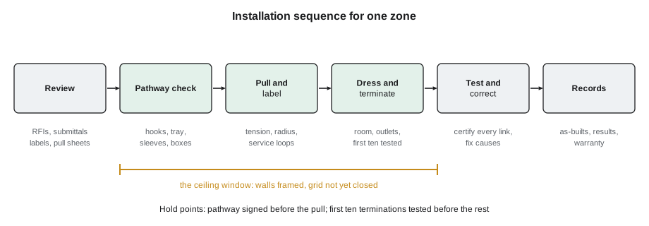
Horizontal cabling has a narrow window on a commercial floor. It cannot be pulled until the ceiling pathway is installed and the walls are framed, and it must be pulled before the ceiling grid closes and the walls are boarded on both sides. Inside the window, other trades are working in the same space: electricians, sprinkler fitters, duct installers and the ceiling crew. Dev attends the general contractor's weekly coordination meeting and books the ceiling areas his crew will need, one zone at a time.
The sequence for each zone is the same. First the pathway is checked: J-hooks installed and spaced correctly, tray complete, sleeves through the walls, pull strings in any conduit. Then the cables are pulled, labeled with pull labels and left coiled at the outlets and on the ladder rack in the room. The walls are boarded and the outlet boxes are cut in. The cables are then dressed in the room, terminated at both ends and tested. Testing usually happens after the ceiling is closed, which is why the pull itself has to be done right the first time.
Crew, tools and safety
A typical horizontal crew is two or three people: a puller at the room end feeding and managing the cable from the boxes, one or two in the ceiling guiding the bundle along the pathway, and a lead who checks routes, keeps the pull sheet and makes sure nothing exceeds the limits this course will set out. On the sixth floor, Dev runs two crews in parallel in different zones, with Maya leading one and a journeyperson, Renée Lachance, leading the other.
The work is mostly overhead, so the hazards are the ones LVT-110 covered: ladders and lifts, falling objects, sharp ceiling edges, dust from drilling, and live electrical equipment in ceilings and rooms. Greta, Cobalt Line's safety coordinator, reviews the floor's hazard assessment with each crew before the pull. Two items are particular to this floor: the base building's sprinkler mains run low near the core, and the existing electrical panels in the core corridor are live. The crew may not open any electrical enclosure, and pulls past the panels use a spotter.
| Tool or item | Used for | Planning note |
|---|---|---|
| Box dispensers or a cable tree | Feeding several cables at once without tangles | One box per cable in the bundle |
| Fish tape, glow rods and pull string | Getting a line through walls and over obstructions | Pull string left in each conduit for the future |
| Pulling grip or tape-and-loop end | Attaching the bundle to the pull line | Never pull by the conductors |
| Hook-and-loop ties | Bundling without crushing the cable | Cable ties are not used on Category 6A |
| Cable labels and printer | Temporary pull labels and permanent identifiers | Printed before the pull |
| Punch-down and termination tools | Terminating jacks and panels | Manufacturer's tool where the warranty requires it |
| Certification tester and adapters | Testing permanent links and channels | Calibration certificate current |
The quality plan
The quality plan says how the crew will know that the work is right before the tester does. It has three kinds of checks. Inspections happen during the work: Maya walks each route after the pull, looking at J-hook spacing, bundle sag, bend radius at every turn and separation from power. Hold points stop the work until something is checked: no zone is closed in until Dev has signed its pathway inspection, and no termination starts until the first ten of each type have been tested. Records collect the evidence: pull sheets, inspection checklists, test results and photographs of the room and zone boxes before the covers go on.
Testing the first ten terminations is one of the most useful habits in the trade. A crew that terminates 48 jacks with a slightly too-long untwist, or 48 panel ports with one pair reversed, has 48 links to redo. A crew that tests the first ten finds the problem after ten. Dev learned the rule the hard way on a school job early in his career, and Maya has written it into every zone's plan.
Worked problem
Planning the boxes for zone Z5
Zone Z5 serves 12 desks with cut lengths, including slack, from 155 ft to 200 ft. Maya wants to pull six cables at a time from six boxes of 1,000 ft. How many six-cable pulls can she make before the first box runs out, and what is left?
Show solution
- Pull the longer six first, at about 200 ft each in the worst case.
- One box supplies one cable per pull. After the first pull of the long six, each box has 1,000 − 200 = 800 ft left.
- The second pull uses the shorter six, at up to about 178 ft, leaving about 622 ft in each box.
- The remaining 622 ft per box is enough for three more pulls of 200 ft in the next zone, so the boxes move on with the crew.
Answer: Two pulls cover Z5 and leave each of the six boxes about two thirds full for the next zone, with nothing wasted.
Common mistakes
MistakeOrdering cable before the submittals are approved.
InsteadWait for approval, or order only what the approved product list already covers.
MistakeLeaving outlet numbering until termination.
InsteadFix the identifiers and print the labels before the pull.
MistakePulling cables from whatever box is nearest.
InsteadPlan which box supplies which cable and save short ends for short runs.
MistakeTerminating a whole zone before testing any of it.
InsteadTest the first ten terminations of each type and correct the method early.
MistakeTreating the warranty as automatic.
InsteadUse only listed components, certified installers and complete test records.
Summary and key terms
- The installation plan turns a cabling design into a scope, schedule, materials list and quality plan.
- Questions found in the documents go to the designer as requests for information before the work starts.
- Submittals and the manufacturer's approved product list decide which components may be used and protect the system warranty.
- Cable takeoffs become an order of boxes, with pulls planned so that boxes empty with little waste.
- Permanent labels are made before the pull, and pull sheets record each cable's box and length marks.
- Horizontal cabling must fit the window between framing and the ceiling grid, zone by zone.
- Inspections, hold points, early testing of the first terminations and complete records make up the quality plan.
- Installation plan
- The contractor's document that sequences the work with people, materials and dates.
- Submittal
- Product data, certifications and samples sent for the consultant's approval before materials are ordered.
- Approved product list
- A manufacturer's list of the components that may be combined under its system warranty.
- Pull sheet
- A list of the cables in one pull or zone, with identifiers, outlet locations, lengths and source boxes.
- Hold point
- A step at which work stops until a required inspection or test has been completed and accepted.
- Attic stock
- Spare material left with the owner at handover, as the specification requires.
Practice problems
Work each problem on paper first, then reveal the answer to check.
A box holds 1,000 ft. How many cables of 190 ft can be cut from it, and what is left?
Show answer
Five cables use 950 ft, leaving 50 ft.
A pod needs 12 cables averaging 170 ft plus 11 ft of slack. About how many feet of cable is that?
Show answer
12 × 181 ≈ 2,170 ft, a little over two boxes.
Why are permanent labels printed before the pull?
Show answer
It forces the outlet numbering to be settled before the cable is installed, avoiding relabeling.
What three things must be true for a manufacturer's system warranty to apply?
Show answer
Listed components only, a certified installer, and every link tested with the results submitted.
Lesson quiz · 5 questions
Score 60% or more to complete this lesson.
Create a free account to save your progress, take quizzes and earn a certificate.