
IRW-320 · Lesson 6 of 12 · 23 min
Storefronts and entrances
▶ Video coming soon A video version of this lesson is on the way.
On Wednesday, November 11, the crew set the entrance canopy outriggers. The morning was cold and still, Crossbeam's telehandler was on site, and the four galvanized tube outriggers lay on dunnage in front of the lobby, each tagged with its piece mark. Shay had watched the canopy go from drawing to steel in three days: on Monday he had checked the column plates, on Tuesday he had read sheet C-2 in the trailer, and now Benno was rigging the first outrigger to the telehandler's forks with a pair of short slings. "The canopy is the first thing anyone sees," Lionel said. "Doctors, patients, the owner. Nobody will look at the beams again. They'll look at this every day."
This lesson explains storefront systems and entrances, the kinds of entrance doors and their hardware, accessibility at entrances, vestibules, canopies and how they are supported, and how entrance steel is installed and coordinated with the glazing contractor.
Storefront
Storefront is a lighter cousin of curtain wall: aluminum framing with glass, used for ground-floor walls and entrances where the height is limited, usually up to one story. Unlike curtain wall, storefront is usually set within an opening, between the floor and a head member above, with the frame anchored at the sill, jambs and head. It is a common product of glazing manufacturers, sold as a system with frames, doors and hardware designed to work together.
- The sill sits on the floor slab or on a steel or concrete curb, with a sill flashing and a receptor to manage water.
- The jambs anchor to the opening's sides, often steel columns or tube posts.
- The head anchors to a steel member above, usually a tube, an angle or the underside of a beam, which must allow the structure above to deflect without loading the glass.
- Doors sit in frames that are part of the system, with hinges or pivots and closers, and often with an automatic operator.
Storefront is a glazing contractor's product, but the steel it anchors to is not. At Ashcroft, the lobby had a short run of storefront on each side of the main entrance, set in steel tube frames that Crossbeam had installed with the lobby framing. The glazing contractor's drawings showed the anchor locations, and Lionel's crew checked the tube frames against them on Monday.
Entrance doors
Entrance doors are the most-used moving parts in a building, and their design depends on traffic, weather and accessibility. The common kinds are these.
- Swing doors on hinges, pivots or continuous hinges, with closers; the usual door for most buildings.
- Balanced doors, which pivot near one edge so they open easily against wind and stack pressure, common at busy entrances.
- Automatic sliding doors, which open on a sensor and suit hospitals and clinics, where people carry things or use wheelchairs.
- Revolving doors, which reduce air leakage at tall buildings and busy entrances, usually with a swing door beside them.
Ashcroft's main entrance had a pair of automatic sliding doors at the outer vestibule wall and a second pair at the inner wall, as the clinic's owner had asked for patients with mobility aids. The door operators sat in a header across the top of each opening, and the header bolted to the steel tube head that Crossbeam had installed. The operators would be installed by Sunbridge with the storefront, and wired by the electrician.
Accessibility at entrances
The 2010 ADA Standards for Accessible Design, which apply to public accommodations and commercial facilities in the US, require accessible entrances with a clear opening of at least 32 in, measured from the face of the open door to the stop, level maneuvering clearances on both sides of the door, thresholds no higher than 1/2 in (with a beveled edge above 1/4 in) and vestibules deep enough that a wheelchair can clear one door before the next opens. Automatic doors must meet the ANSI/BHMA standards for power-operated doors.
Worked problem
Checking a clear opening
The inner vestibule doors at Ashcroft are a pair of sliding leaves that each open 36 in. The frame detail shows that, fully open, each leaf's edge stops 3/4 in short of the jamb face. What is the clear opening of the pair, and does it meet the 32 in minimum for an accessible door?
Show solution
- Clear opening = 2 × (36 − 3/4) = 2 × 35 1/4 = 70 1/2 in.
- 70 1/2 in is well over 32 in.
Answer: About 70 1/2 in, far more than required, which suits a clinic where patients may use wheelchairs, walkers or stretchers. The steel framing had to be set to the exact opening width the door maker's drawings gave, which is why Lionel checked the tube frame width with a tape at the top, middle and bottom.
Vestibules
A vestibule is a small entry space between two sets of doors. It reduces the air that rushes in when the doors open, saving energy and keeping the lobby comfortable, and energy codes require vestibules at many entrances. The vestibule must be deep enough for its purpose: for accessibility, a wheelchair must be able to clear one door before the next must open, and for energy, the doors must not both be open at once in normal use. Ashcroft's vestibule was about 8 ft deep between door lines, set by the architect to suit both rules.
From the misc crew's side, a vestibule means two parallel lines of steel framing for the door frames and storefront, plus heads and sometimes a small roof or ceiling frame. The two lines must be parallel, square to the building and at the same floor elevation, because the doors are designed as a pair.
Canopies
Canopies protect an entrance from rain and snow and mark it architecturally. They range from small cantilevered hoods to large frames on columns. Steel canopies are usually one of three types.
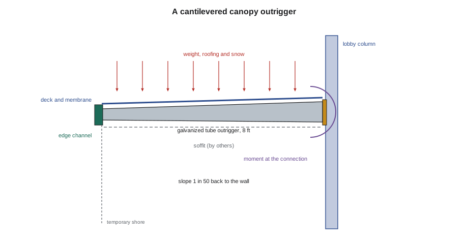
- Cantilevered from the building, with outriggers bolted or welded to the building's frame; the outrigger connection carries both the weight and a bending moment.
- Hung from above by tie rods back to the building, with a pinned connection at the wall; the rods carry the weight in tension.
- Supported on their own columns at the outer edge, with a simple connection at the building.
Ashcroft's canopy was the first type: four galvanized rectangular tube outriggers, each 8 ft long, cantilevered from the lobby frame at 10 ft spacing across the 30 ft width. A steel edge channel along the front and three purlins between the outriggers carried a metal deck. A roofing membrane on top, a gutter at the back and an aluminum soffit underneath would follow from other trades.
Worked problem
Loads on the canopy outriggers
The Ashcroft canopy is 30 ft wide and projects 8 ft. For this lesson, use a SAMPLE combined design load of 25 psf over the canopy area for its weight, roofing and snow. Four outriggers share the load equally. What load does each carry, and what bending moment does it put into its connection, taking the load at the middle of the projection, 4 ft from the wall?
Show solution
- Canopy area = 30 × 8 = 240 ft².
- Total load = 240 × 25 = 6,000 lb.
- Per outrigger = 6,000 ÷ 4 = 1,500 lb.
- Moment at the connection = 1,500 × 4 = 6,000 lb·ft.
Answer: About 1,500 lb and 6,000 lb·ft at each connection. The moment is carried by the end plate and its bolts, with the top bolts in tension, so they must be installed and tightened exactly as specified. Real snow loads at an entrance can be much larger where snow drifts from a higher roof or slides off the wall above, which the engineer allows for.
Canopies are designed by an engineer, and their connections are often the most heavily loaded small connections on a building. Shoring the outer edge while the canopy is completed is common, because a cantilever is not stable until its connection is complete and, on some designs, until the deck or bracing is installed.
Setting the Ashcroft canopy
The work on Wednesday followed the plan Lionel had written on Tuesday afternoon. Before the first pick, Shay and Benno checked the four column plates against sheet C-2 revision 2: hole pattern, plate size and elevation. All four matched. Then each outrigger was lifted on the telehandler with two short slings at its balance point and a tag line, raised to the plate, and bolted with four high-strength bolts through its end plate, snugged first and then pretensioned with the turn-of-nut method Nate had taught at the Wednesday steel nights. Rhea checked the slope of each outrigger with a digital level: the drawing called for a slope of 1 in 50 back toward the wall, so that water would drain to the gutter.
A shore post went under the tip of each outrigger until the edge channel and purlins were bolted, because the drawing note required the canopy to be shored until the edge channel was complete. By two in the afternoon all four outriggers, the edge channel and the purlins were in. The deck would follow on Thursday, set by Benno with self-drilling screws as the drawing showed, and the shores came out on Friday morning after Lionel checked every bolt.
The slope was the point Lionel checked most carefully. "A canopy that drains toward the doors puts water on the sidewalk where people walk, and in winter that's ice," he said. Three outriggers came in at the right slope; the fourth was a little flat, at about 1 in 80. It was within the adjustment of its slotted purlin connections, so Rhea shimmed the purlin seat to bring the deck to the right slope without changing the outrigger's connection.
Coordinating with the glazing contractor
Entrance steel and glazing depend on each other, and the trades must agree on several points before either starts: the anchor locations for the storefront and door headers, the deflection the head steel will have under load, the joints between steel and aluminum where sealant will go, the flashing at the canopy and the head of the storefront, and the order of work. At Ashcroft, Sunbridge's drawings showed the head deflection the storefront could accept, 1/4 in under live load, and Lionel's crew made sure the tube head was supported as the engineer had designed. Mina also asked that the steel surfaces where her sealant would bond be clean of weld spatter and loose paint, which Lionel added to the protection list.
Hung canopies and tie rods
Many canopies are hung rather than cantilevered. A light outer frame is pinned to the wall at its back edge and held up at the front by tie rods that run up at an angle to connection plates on the building higher up. The rods carry the canopy's weight in tension, and the pin at the wall carries a horizontal push as well as part of the weight. Hung canopies look light and are common on glass entrances, but they have two weaknesses an installer must respect: the rods must be tensioned as the drawing says, neither slack nor overtightened, and the canopy must be held down against wind uplift, which can push the frame up and leave the rods slack.
The tie rods' turnbuckles or threaded ends are adjusted to bring the canopy to its drawn slope, and then locked. Where the rods are architectural, with polished fittings, they are protected and handled like stainless rails. Rhea had installed a hung glass canopy at Larkmont Tower's lobby entrance in 2025, with stainless rods and fittings and laminated glass panels clamped to a steel frame. The glass went on last, after the frame was complete, adjusted and inspected, because a glass canopy cannot be adjusted once the glass is on.
Snow, ice and water at entrances
Entrances face water and ice in ways the rest of a building does not. Snow slides off the wall above onto the canopy, rain runs off the canopy onto the sidewalk if the slope is wrong, and water from the canopy's gutter must go somewhere other than the entry path. Ice forms where meltwater drips and refreezes. The architect designs the drainage, but the installer controls the slope, the gutter's fall and the downspout location. At Ashcroft, the gutter at the back of the canopy drained to a downspout inside the lobby wall, and its outlet had to line up with a scupper in the canopy's back edge that Stonegate had cut to a dimension on the drawing. Shay checked the scupper against the downspout location with a plumb line on Wednesday afternoon, and it matched within a few millimeters.
Protecting finished entrances
An entrance is finished early and used by every trade until the building is done. Door frames are scuffed by carts, canopy fascias are hit by lift baskets and storefront glass is splashed by concrete and paint. Protection plans for entrances include corner guards on frames, plywood over the lower part of storefront, a designated construction entrance elsewhere so that the finished one is not used for deliveries, and a note to the lift operators about the canopy. Tallcorn planned to close the main entrance to construction traffic once the doors were installed in January.
Common mistakes
MistakeSetting door framing to the leaf width instead of the clear opening.
InsteadUse the door maker's frame dimensions and check the clear opening the code requires.
MistakeInstalling canopy outriggers without checking the plates against the latest revision.
InsteadCheck the hole pattern, plate size and elevation first.
MistakeRemoving canopy shores too early.
InsteadLeave shores until the edge members and bracing the drawing requires are complete.
MistakeIgnoring the slope of a canopy.
InsteadCheck the slope so water drains away from the doors.
MistakeLeaving weld spatter where sealant will bond.
InsteadClean and protect steel surfaces that the glazing contractor will seal to.
Summary and key terms
- Storefront is light aluminum and glass framing for ground-floor walls and entrances, set within an opening.
- Entrance doors include swing, balanced, automatic sliding and revolving doors.
- Accessible entrances under the ADA Standards need at least 32 in clear, level maneuvering space and low thresholds.
- Vestibules reduce air infiltration and must be deep enough for accessibility.
- Canopies are cantilevered, hung or column-supported; their connections carry weight and often a bending moment.
- Entrance steel and glazing are coordinated on anchors, deflection, sealant surfaces and the order of work.
- Storefront
- Light aluminum and glass framing for ground-floor openings and entrances.
- Vestibule
- A small entry space between two sets of doors.
- Clear opening
- The width a person can pass through with the door open, measured from the open door face to the stop.
- Outrigger
- A cantilevered member that projects from a building to support a canopy.
- Power door operator
- A motorized device that opens and closes a door.
- Shore
- A temporary support placed under a member until its permanent support is complete.
Practice problems
Work each problem on paper first, then reveal the answer to check.
A single sliding door opens 40 in and stops 1 in short of the jamb. What is its clear opening?
Show answer
39 in.
A canopy is 20 × 6 ft with a load of 25 psf on three outriggers. What does each carry?
Show answer
120 ft² × 25 = 3,000 lb ÷ 3 = 1,000 lb.
Why is a canopy shored during installation?
Show answer
A cantilever is not stable until its connection and edge members are complete.
Why does a canopy slope back to the wall?
Show answer
To drain water to the gutter, away from the doors.
What does a vestibule do?
Show answer
It reduces the air that enters when doors open and keeps the lobby comfortable.
Lesson quiz · 5 questions
Score 60% or more to complete this lesson.
Create a free account to save your progress, take quizzes and earn a certificate.