
IRW-310 · Lesson 8 of 12 · 21 min
Erection engineering and temporary works
▶ Video coming soon A video version of this lesson is on the way.
Odette Hollister came to the November 6 session in person, carrying a folder thicker than Carla's drawings. She was Lakeport's erection engineer, and she had written the procedures for Larkmont, Ravensworth and the Ashcroft truss. "Everybody thinks the building is designed once," she said. "It's designed twice. The engineer of record designs the finished building. I design the building as it is on every day before it's finished: half-built, unbraced, with a crane hanging off it and wind blowing through it. That second building doesn't exist on any drawing unless someone draws it."
This lesson covers erection engineering: who is responsible for stability during erection, what an erection procedure contains, temporary works such as guys, shoring, falsework and lifting devices, how temporary works are installed, inspected and removed, and how changes on site are handled.
Who is responsible for what
In the United States, AISC 303, the Code of Standard Practice for Steel Buildings and Bridges, divides responsibilities. The engineer of record designs the completed structure and identifies on the drawings any non-self-supporting steel frame, one that depends on other elements such as concrete walls or floors for stability, and any special erection conditions the design depends on. The erector is responsible for the means and methods of erection, and for the stability of the structure during erection, including the design of temporary bracing and supports, which on larger jobs is done by an erection engineer, a professional engineer working for the erector or the fabricator. OSHA 1926.754(a) requires that structural stability be maintained at all times during erection.
Odette's point was that the erection engineer's design is no less real for being temporary. A guy, a shoring tower or a lifting lug carries real loads, and if it fails the frame can fall as surely as if a permanent beam had failed.
What an erection procedure contains
An erection procedure, sometimes called an erection plan or erection analysis, is a set of drawings and notes prepared and sealed by the erection engineer. For a tower, it typically includes:
- The erection sequence, tier by tier and bay by bay, showing the order in which members are set and connected.
- The minimum connections before the crane may release each kind of member: for example, the number of bolts at a beam end, or the bolts at a column splice.
- Temporary bracing and guying, with locations, sizes, anchors, pretension and the conditions for removal.
- Limits on how far erection may run ahead of bolting, welding, bracing, decking and concrete.
- Design wind speeds for erection, and what must be done when they are exceeded: stop, add bracing, or secure loose material.
- Construction loads the partly built structure may carry: deck bundles, stored steel, equipment, and where they may be placed.
- Shoring, falsework and temporary supports, with their capacities and foundations.
- Lifting devices: pick points, lugs, spreaders and their capacities, and the rigging for engineered lifts.
- Survey and plumbing checks and the tolerances to be met before final connections.
The procedure is reviewed by the engineer of record for its effect on the permanent structure, and by the general contractor for coordination with other trades. It is issued to the site with a revision number, and the foreperson has the current version.
Temporary bolting rules
The minimum bolting before release is one of the most important parts of the procedure. OSHA 1926.756(a) requires at least two bolts per connection, of the same size and strength as shown on the drawings, wrench-tight or the equivalent the engineer specifies, before the hoisting line is released from a solid-web member. Larkmont's procedure also required at least half the permanent bolts in every brace connection before the brace was released, and the erection plate bolts and at least four flange bolts per side at each column splice.
Worked problem
Bolts before releasing a brace
A Larkmont core brace has 12 bolts at each end connection. The procedure requires at least half the permanent bolts before the crane releases the brace. How many bolts go in at each end before release, and how many in all for a bay with four braces?
Show solution
- Bolts before release at one end = 12 × 0.5 = 6.
- Each brace has two ends: 6 × 2 = 12 bolts per brace before release.
- Four braces: 12 × 4 = 48 bolts before the crane is free.
Answer: Six at each end, 48 for the bay. The connectors carried bolt bags with the count marked on them, so that nobody had to remember the rule halfway up a brace with a crane waiting.
Temporary works
Temporary works are anything built to make the permanent work possible and then removed: guys, struts, shoring towers, falsework, temporary columns, lifting lugs and frames, work platforms, safety cable stanchions and crane tie-ins. On a large job the temporary works can be a structure in their own right.
- Guys and struts hold frames plumb and stable until permanent bracing and floors are complete.
- Shoring towers carry members such as transfer girders, long trusses or cantilevers until they are connected and their supports complete.
- Falsework carries bridge girders and other members during splicing and setting.
- Lifting lugs and frames are welded or bolted to pieces for lifting; they are designed and inspected like any other lifting gear.
- Temporary columns or hangers support part of a structure, for example where a transfer girder will later carry columns.
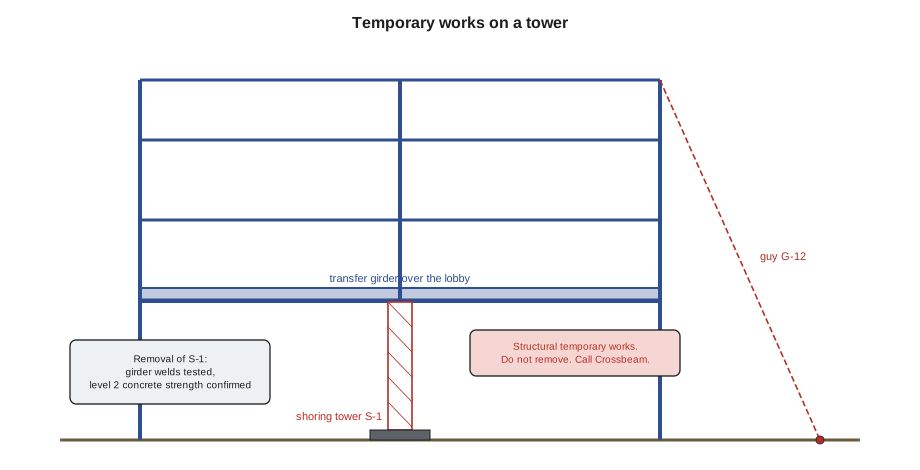
The transfer girder at Larkmont
Larkmont's lobby transfer girder, the 40 ft W36×194 from lesson 2, carried two columns from the floors above, which stopped at the girder rather than running to the ground. Until the girder's end connections were fully welded and tested and the concrete of level 2 had gained strength, Odette's procedure required a temporary shoring tower under the middle of the girder, standing on the ground floor slab on a steel spreader plate. The tower was rated for the load of the girder and the steel and wet concrete of three floors above it; the procedure allowed no more than three floors to be built above the girder before the shoring was released.
Releasing the shoring was itself a step in the procedure. The girder's welds were tested, the concrete strength was confirmed by the testing lab, Odette inspected the girder and gave a written release, and only then did the crew back off the shoring tower's screw jacks, slowly and evenly, while a surveyor watched the girder's deflection. It came down 1/4 in, close to the 9/32 in Odette had predicted.
Installing, inspecting and removing temporary works
The crew installs temporary works exactly as the procedure shows. A guy at a different angle, a turnbuckle of a smaller size, a clip installed backwards or an anchor in the wrong place changes the design, and the crew must not improvise. Where something cannot be built as shown, the foreperson stops and calls the engineer.
Temporary works are inspected when installed and then regularly, usually daily, and after high wind or any impact. Crossbeam used a temporary works register at Larkmont: every guy, shore and temporary support had a number, a tag, its installation date, the inspections and the removal condition. Removing any item needed the foreperson's signature and, where the procedure said so, the engineer's written release. Tags read "Structural temporary works. Do not remove or alter. Call Crossbeam" with a phone number, as lesson 4 described.
| Item | Installed | Removal condition | Release by |
|---|---|---|---|
| G-12 guy, gridline 1 at C | Mar 24, 2025 | End-wall moment welds tested, levels 2–3 | Foreperson |
| G-13 guy, gridline 1 at D | Mar 24, 2025 | End-wall moment welds tested, levels 2–3 | Foreperson |
| S-1 shoring tower, lobby girder | Apr 2, 2025 | Girder welds tested; level 2 concrete strength confirmed | Erection engineer, in writing |
| T-1 crane tie-in beams, level 8 | Jul 14, 2025 | Crane dismantled | Crane engineer and general contractor |
Changes on site
No erection runs exactly as planned. Pieces arrive late or out of sequence, a crane is down, a floor is behind, or a member does not fit. Each of these can tempt the crew to change the sequence, and some changes are harmless while others make the frame unstable. The rule is that any change to the sequence, the temporary works or the minimum connections goes to the erection engineer before it is made. A phone call and a marked-up sketch, followed by a revised procedure, is normal; a change made on site because it seemed sensible is not.
At Larkmont, in June, the core braces for tier 4 arrived two days late. Carla wanted to keep the gang busy by setting the perimeter beams of tier 4 without the core braces. She called Odette, who allowed it with two additional temporary guys per side and a limit of one floor of perimeter beams until the braces arrived. The extra guys went in, the braces came, and the guys came out on her release. "That's how it should work," Odette told the group. "I'd much rather get a call at six in the morning than a call at six at night saying something moved."
Lifting devices
Lifting lugs, padeyes, trunnions and lifting frames are temporary works too. They are designed for the load with a safety factor, welded by qualified welders to a procedure, and often inspected by testing before use. A lug welded on site without design, or a hole burned in a flange for a shackle, is not a lifting point. Below-the-hook lifting devices such as spreader beams and lifting frames are marked with their rated load and inspected as their standards require: ASME B30.20 in the United States, and in Canada the same standard is widely used along with the maker's instructions.
Reading an erection procedure on site
An erection procedure is written for engineers and forepersons, and it can look dense, but the parts the crew needs are usually in a few places: the sequence drawings with numbered steps, the table of minimum connections, the temporary works drawings with their removal conditions, and the general notes on wind and construction loads. Carla's habit at Larkmont was to read the relevant pages with the gang at the start of each tier, at the gang box, and to mark the day's steps on a copy. When the procedure said "do not proceed to step 7 until step 6 is complete and surveyed", the gang knew exactly what step 6 meant.
The procedure also shows what is not the crew's decision. Pretension for guys, the capacity of a shoring tower, the welding sequence for a transfer girder, the conditions for releasing temporary works: these are the engineer's. If the site cannot meet them, the answer is a call, not an improvisation.
Temporary works on other trades' structures
Erectors often attach temporary works to things they did not build: guys anchored to concrete slabs, struts bearing on walls, shores standing on floors. Each of these needs the owner of that structure, usually through the general contractor and its engineer, to confirm that it can take the load. Guy anchors in concrete are designed and installed to the anchor maker's instructions, with the concrete strength confirmed, and are proof-tested where the procedure requires. A shore on a slab may need the slab below it to be reshored, as concrete contractors do with their formwork. At Larkmont, the shoring tower under the transfer girder stood on the ground floor slab only after Wexmoor's engineer had confirmed the slab and the soil below could take the load.
Records that protect everyone
The temporary works register, the procedure revisions, the engineer's releases, the inspection records and the daily reports are the evidence that the frame was kept stable at every stage. If something goes wrong, they show what was done and when; if nothing goes wrong, they show the next job how it was done. Crossbeam kept Larkmont's register for seven years, as its quality program requires.
Wind design for erection
The erection engineer designs temporary works for wind, but usually for a lower wind than the finished building, because the partly built frame stands for weeks or months rather than for its whole life. The procedure states the design wind and what must happen if a storm stronger than that is forecast: extra guys, securing loose materials, removing large surfaces such as tarps or stacked panels, or not erecting certain pieces until the storm has passed. The foreperson reads the forecast against that number, and Odette's procedures always printed it on the first page.
Common mistakes
MistakeTreating temporary works as less important than permanent steel.
InsteadBuild, inspect and remove temporary works exactly as designed; they carry real loads.
MistakeChanging the sequence on site because it seems sensible.
InsteadCall the erection engineer first and follow the revised procedure.
MistakeRemoving a shore or guy because the next trade wants the space.
InsteadRemove only when the register's condition is met and the release is signed.
MistakeWelding an unplanned lifting lug.
InsteadUse only designed and inspected lifting points.
MistakeReleasing a member with fewer bolts than the procedure requires.
InsteadInstall the minimum connections before the crane lets go.
Summary and key terms
- The engineer of record designs the finished structure; the erector, usually through an erection engineer, is responsible for stability during erection.
- The erection procedure sets the sequence, minimum connections, temporary bracing, limits, wind, construction loads, shoring, lifting devices and survey checks.
- OSHA 1926.756(a) requires at least two bolts per connection before release; the procedure may require more.
- Temporary works include guys, struts, shoring, falsework, temporary columns and lifting devices; each is designed, installed as shown, inspected and tagged.
- A temporary works register records each item, its inspections and its removal condition.
- Changes to sequence or temporary works go to the erection engineer before they are made.
- Erection engineer
- A professional engineer who designs the structure's stability and temporary works during erection.
- Erection procedure
- The erection engineer's sealed drawings and notes for sequence, bracing, limits and temporary works.
- Temporary works
- Structures built to make the permanent work possible and then removed.
- Shoring tower
- A temporary tower that supports a member until its permanent supports are complete.
- Temporary works register
- A list of each temporary works item with its inspections and removal conditions.
- Transfer girder
- A girder that carries columns from the floors above where they do not continue to the ground.
Practice problems
Work each problem on paper first, then reveal the answer to check.
A brace end has 10 bolts and the rule is half before release. How many bolts at each end?
Show answer
5.
A bay has six braces with 10 bolts at each end. How many bolts before release?
Show answer
5 × 2 × 6 = 60.
Who may release a shoring tower under a transfer girder?
Show answer
The erection engineer, in writing, once the conditions are met.
A guy cannot be anchored where shown. What does the foreperson do?
Show answer
Stop and call the engineer; do not improvise.
When are temporary works inspected?
Show answer
When installed, regularly (usually daily), and after high wind or any impact.
Lesson quiz · 5 questions
Score 60% or more to complete this lesson.
Create a free account to save your progress, take quizzes and earn a certificate.