
HSE-224 · Lesson 7 of 12 · 30 min
Establishing an electrically safe work condition
The electrically safe work condition, often shortened to ESWC, is the goal of almost every electrical job. It is the state in which the conductors or circuit parts to be worked on have been disconnected from energized parts, locked and tagged, tested to verify the absence of voltage and, where necessary, temporarily grounded. Until every one of those steps is complete, the equipment must be treated as energized, and the work done to reach the ESWC is itself energized work. This lesson works through the eight-step process, the test-before-touch discipline and the special problems of back-feed, stored energy and induced voltage.
HSE-210 covers hazardous energy control in general, including lockout programs under OSHA 1910.147. This lesson concentrates on the electrical specifics in 1910.333(b) and NFPA 70E Article 120.
Until it is proven dead, it is live
NFPA 70E 120.6 is explicit that electrical conductors and circuit parts are not considered to be in an electrically safe work condition until all the requirements of the process have been met. Until then, the work involved in opening disconnects, verifying absence of voltage and applying grounds requires the same risk assessment and PPE as any other energized work. OSHA 1910.333(b)(2)(iv)(B) requires a qualified person to use test equipment to verify that circuit elements and equipment parts are de-energized, and to verify that the test equipment is operating properly before and after the test if the circuit is over 600 V.
This is the most important idea in the lesson. Every electrician has seen a breaker that was off but whose load side was still live because of a second feed, a backfeed through a generator or a control transformer, a mislabeled panel or a failed contact. The only way to know a conductor is dead is to test it, at the point of work, with a tester that has been proven to work.
The eight steps
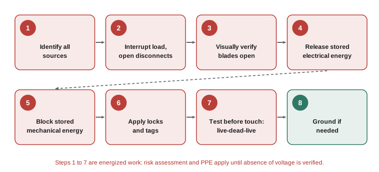
NFPA 70E-2024 section 120.6 (numbered 120.5 in the 2021 edition) and CSA Z462 set out the same eight-step process for establishing and verifying an electrically safe work condition:
- Step 1: Determine all possible sources of electrical supply to the specific equipment. Check applicable up-to-date drawings, diagrams and identification tags.
- Step 2: After properly interrupting the load current, open the disconnecting device for each source.
- Step 3: Wherever possible, visually verify that all blades of the disconnecting devices are fully open or that drawout-type circuit breakers are withdrawn to the fully disconnected position.
- Step 4: Release stored electrical energy, for example by discharging capacitors.
- Step 5: Release or block stored nonelectrical energy in devices to the extent that the circuit cannot be unintentionally energized, for example springs in breaker operating mechanisms.
- Step 6: Apply lockout devices in accordance with a documented and established procedure.
- Step 7: Use an adequately rated portable test instrument to test each phase conductor or circuit part at each point of work to verify it is de-energized. Test each phase conductor or circuit part both phase-to-phase and phase-to-ground. Before and after each test, determine that the test instrument is operating satisfactorily through verification on any known voltage source.
- Step 8: Where the possibility of induced voltages or stored electrical energy exists, ground the phase conductors or circuit parts before touching them. Where it could reasonably be anticipated that the conductors could contact other exposed energized conductors, apply temporary protective grounding equipment rated for the available fault duty.
The 2024 edition clarified step 7 to require testing each phase conductor or circuit part at each point of work. That matters for multi-section switchboards, equipment with several compartments and long cable runs, where one point may be de-energized while another is not. It also added a note that a neutral conductor may still carry current after phase conductors are de-energized, for example from other circuits sharing it.
Step 1 in practice: finding every source
Most serious failures of the ESWC process start in step 1. Equipment may be fed from more sources than its label suggests. Common hidden sources include:
- A second utility feed or a tie breaker in a double-ended substation.
- A standby generator, through an automatic transfer switch that may operate on loss of normal power.
- An uninterruptible power supply, which is designed to keep supplying the load when its input is removed.
- Solar photovoltaic systems, batteries and other distributed generation that can back-feed through an inverter.
- Control power supplied from a different panel, so the control wiring stays live after the main disconnect is open.
- Capacitors for power factor correction, variable frequency drive DC buses and snubber circuits.
- Potential transformers and control power transformers that can back-feed high voltage if energized from their secondary side.
- Mislabeled or modified circuits, where the panel directory no longer matches reality.
Worked problem
Finding the hidden source
An electrician must replace a contactor in a pump control panel. The panel label reads "Fed from MCC-2 bucket 4C". The drawings show the pump also has a 120 V control circuit for its alarm, fed from lighting panel LP-3, and a heater in the panel fed from the same lighting panel. List the sources and the disconnects needed.
Show solution
- Main power: MCC-2 bucket 4C, at 600 V (or 480 V).
- Control and alarm circuit: a breaker in LP-3, at 120 V.
- Panel heater: a second breaker in LP-3, at 120 V.
- All three must be opened, locked and verified at the point of work. Opening only the MCC bucket would leave two 120 V circuits live inside the panel.
Answer: Three sources: the MCC bucket and two breakers in LP-3. Drawings and an on-site check of every conductor entering the enclosure are needed to find them all.
Step 7 in practice: test before touch
Step 7 is often called test before touch, and the method is often called live-dead-live:
- Live: verify that the tester works on a known live source of similar voltage, or on a proving unit designed for the purpose.
- Dead: test each phase conductor or circuit part at the point of work, phase to phase and phase to ground. For a three-phase system that means A-B, B-C, C-A, A-G, B-G and C-G, plus neutral to ground where present.
- Live: verify again that the tester works on the same known source, to prove it did not fail during the test.
The tester must be adequately rated for the voltage and the installation category of the location (Lesson 9), in good condition and used by someone trained in its use. A non-contact voltage detector, the pen-type tester that beeps near a live conductor, is not an adequate instrument for verifying absence of voltage. It is useful for a quick check before touching, but it can miss a live conductor that is shielded, DC or at an unusual voltage, and it says nothing about phase-to-phase voltage.
Worked problem
Counting the tests at a three-phase point of work
An electrician has locked out a 277/480 V, three-phase, four-wire feeder and must verify absence of voltage at a junction box. How many measurements are needed, counting the before and after checks on the proving unit?
Show solution
- Phase to phase: A-B, B-C, C-A, giving 3 measurements.
- Phase to ground: A-G, B-G, C-G, giving 3 measurements.
- Neutral to ground: N-G, giving 1 measurement, since the neutral may carry current from other circuits.
- Proving checks: 1 before and 1 after.
- Total: \( 3 + 3 + 1 + 2 = 9 \).
Answer: Nine measurements. Skipping any of them leaves a path that has not been proven dead.
Absence of voltage testers
An absence of voltage tester (AVT) is a permanently mounted device, installed in the equipment, that automatically checks its own function, tests every phase to every other phase and to ground, and shows a clear indication when the equipment is de-energized. AVTs are listed to UL 1436, which includes specific requirements for absence of voltage testers. The standards allow a permanently mounted AVT to be used in place of a portable tester for step 7, provided it is listed and labeled for that purpose and installed according to the manufacturer's instructions, and the employer's procedure covers its use.
The benefit is that the worker can verify absence of voltage without opening the enclosure, which removes much of the shock and arc flash exposure from step 7. AVTs are increasingly specified in new motor control centers and machine control panels, but they must still be part of a documented procedure, and they only verify the conductors at the point where they are connected.
Stored energy
Capacitors in power factor correction banks, variable frequency drives, uninterruptible power supplies, welders and some test equipment can hold a lethal charge after the supply is removed. Many have bleed resistors that discharge them within a few minutes, but resistors fail. Step 4 requires stored electrical energy to be released, usually by waiting the time specified by the manufacturer and then verifying with a meter, or by using a rated grounding stick or discharge tool. Step 5 covers nonelectrical energy, such as charged springs in breaker operating mechanisms, which can close a breaker unexpectedly.
Worked problem
Waiting for a drive DC bus to discharge
A 600 V variable frequency drive has a DC bus that charges to about 810 V DC. Its label says to wait 15 minutes after removing power before opening the cover. After 15 minutes, the electrician measures 610 V DC across the DC bus terminals. What should happen?
Show solution
- The expected value after the wait is close to zero; 610 V DC means the bleed resistor or discharge circuit has probably failed, or a source is still connected.
- 610 V DC is in the 301 V to 1 kV row of the DC boundary table, so the restricted approach boundary still applies.
- The electrician should close the cover, verify that every source is open, and then use a properly rated discharge tool according to the manufacturer's instructions, or call for help.
- After discharge, the electrician re-tests, using live-dead-live.
Answer: The drive is not in an electrically safe work condition. Stored energy must be safely discharged and verified before any work starts.
Temporary protective grounding
Step 8 applies when induced voltage or stored energy is possible, or when the de-energized conductors could be re-energized accidentally by contact with other energized conductors. This is common at medium and high voltage, on long cable runs and overhead lines that run parallel to energized circuits, and wherever a fault elsewhere could back-feed. Temporary protective grounding equipment connects the phases together and to ground, creating an equipotential zone so that if the conductors are energized, the protective devices operate quickly and the voltage across the worker is limited.
Grounding sets must be rated for the available fault current and clearing time (in North America, ASTM F855 specifies them), installed with a hot stick after verifying absence of voltage, and removed in the reverse order. They must be inspected before each use and kept in good condition. Grounds are not normally needed on low voltage equipment in buildings, but the risk assessment decides.
Keeping it safe and restoring power
Once established, the electrically safe work condition must be maintained. Every worker who may be exposed applies their own lock. If the job is left overnight, locks remain in place and the process is repeated, including testing, before work resumes. When the work is complete, the crew follows the employer's procedure for restoring power: tools and grounds removed, guards and covers replaced, everyone accounted for and clear, locks removed by the people who applied them, and the equipment re-energized by a qualified person who has determined it is safe. The 2024 edition of NFPA 70E reinforced that a circuit must not be manually re-energized after a protective device has opened until a qualified person determines it is safe.
Common mistakes
MistakeTrusting the panel directory to identify all sources.
InsteadCheck drawings and every conductor entering the enclosure; panels are often mislabeled.
MistakeUsing a non-contact voltage detector to verify absence of voltage.
InsteadUse an adequately rated contact tester and the live-dead-live method.
MistakeTesting only phase to ground.
InsteadTest phase to phase and phase to ground at each point of work.
MistakeAssuming a drive is safe once the input disconnect is open.
InsteadVerify the DC bus has discharged, waiting the specified time and testing.
MistakeDoing the ESWC steps without PPE because the goal is to de-energize.
InsteadUntil verified, the equipment is energized and PPE is required.
Summary and key terms
- Equipment is energized until all eight ESWC steps are complete.
- Find every source, including generators, UPS, PV, control power and capacitors.
- Open disconnects after interrupting load, verify visibly, release stored energy and lock out.
- Test each phase at each point of work, phase to phase and phase to ground, with live-dead-live.
- Listed absence of voltage testers can replace portable testing when part of the procedure.
- Ground conductors where induced voltage, stored energy or accidental contact is possible.
- Restore power only through a documented procedure and a qualified person's determination.
- Electrically safe work condition (ESWC)
- Disconnected, locked out, tested for absence of voltage and grounded where needed.
- Test before touch
- Verifying absence of voltage at the point of work before contact.
- Live-dead-live
- Proving a tester on a known source before and after testing for absence of voltage.
- Absence of voltage tester (AVT)
- A permanently mounted, self-checking device listed to UL 1436 that verifies absence of voltage.
- Back-feed
- Energy flowing into a circuit from an unexpected direction, such as a generator or inverter.
- Proving unit
- A portable source of known voltage used to check a tester.
- Temporary protective grounding
- Equipment that bonds phases together and to ground to create an equipotential zone.
- Induced voltage
- Voltage produced in a de-energized conductor by nearby energized conductors.
- Bleed resistor
- A resistor that discharges a capacitor after the supply is removed.
Practice problems
Work each problem on paper first, then reveal the answer to check.
List the eight ESWC steps in brief.
Show answer
Identify sources; open disconnects; verify open; release stored electrical energy; block nonelectrical energy; lock out; test; ground if needed.
How many phase-to-phase tests are needed on a three-phase system?
Show answer
Three: A-B, B-C and C-A.
Why is a non-contact detector not enough to verify absence of voltage?
Show answer
It can miss shielded, DC or unusual voltages and does not measure phase to phase.
Which standard lists absence of voltage testers?
Show answer
UL 1436.
What 2024 change affected step 7?
Show answer
Testing each phase conductor or circuit part at each point of work.
What are two hidden sources that can back-feed a panel?
Show answer
A generator through a transfer switch, a UPS, a PV inverter or control power from another panel.
When is temporary protective grounding needed?
Show answer
Where induced voltage, stored energy or accidental contact with energized conductors is possible.
Why test neutral to ground?
Show answer
A shared neutral may carry current from other circuits.
Is PPE required while performing ESWC steps 1 to 7?
Show answer
Yes; until verified, the equipment is treated as energized.
What must happen before re-energizing after a protective device opens?
Show answer
A qualified person must determine it is safe.
Lesson quiz · 5 questions
Score 60% or more to complete this lesson.
Create a free account to save your progress, take quizzes and earn a certificate.