
HSE-221 · Lesson 8 of 12 · 25 min
Isolations and the permit
Most permitted work depends on isolation: separating the equipment from every source of hazardous energy and material, securing that separation so it cannot be undone by accident, and proving it is effective before anyone starts work. HSE-210 covered lockout and hazardous energy control in depth, including the types of energy, lockout devices, verification and group lockout. This lesson looks at isolation from the point of view of the permit system: how isolations are planned, recorded and cross-referenced to permits, how isolation standards are chosen, and how sites manage the many locks and points involved in complex jobs.
Why isolation is central to the permit
Investigations of permit failures show the same story again and again: work was done on equipment that was not properly isolated, or isolations were removed while someone was still working. The permit may have been perfectly filled in, but the isolation behind it was wrong, incomplete or not verified. For this reason, most permit systems treat the isolation certificate as the backbone of the permit for any work that breaks containment or exposes people to energy. If the isolation is not right, nothing else on the permit matters.
Isolation standards
Not all isolations give the same protection. Process industries rank isolation methods by how reliably they prevent the release of hazardous material. The UK HSE's guidance on isolation, HSG253 'The safe isolation of plant and equipment' (2006), is widely used internationally, alongside company standards. A typical hierarchy for process isolation is:
- Positive isolation: complete physical separation, such as removing a spool piece, fitting a spade or blind, or disconnecting a line. This is the most secure method and is usually required for confined space entry and for highly hazardous fluids.
- Double block and bleed: two closed and locked valves with a vented, drained section between them, so that any leakage past the first valve is released safely and can be detected.
- Double block: two closed and locked valves without a bleed. Less secure, because leakage past the first valve builds up between them.
- Single valve isolation: one closed and locked valve. Acceptable only for low-hazard systems, short-duration work, or as a temporary step while a more secure isolation is installed.
For electrical isolation, the hierarchy runs from withdrawing or racking out a breaker and locking it in the disconnected position, through opening and locking a disconnect switch with a visible break, to removing fuses. Electrical isolations must always be proved dead with a tested voltage detector, following the live-dead-live check described in HSE-214.
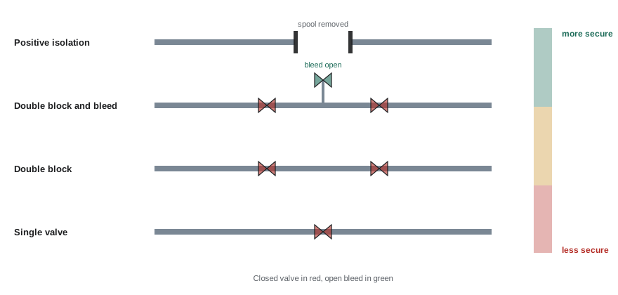
The site's isolation standard should state which method is required for which combination of hazard and task. For example, a site might require positive isolation for any vessel entry and for hydrogen sulfide service, double block and bleed for work on hydrocarbon lines above a certain pressure, and allow single valve isolation only for water and air systems under a set pressure.
Planning isolations
Isolations are planned as part of permit preparation, usually by operations with input from maintenance and engineering. Good planning uses up-to-date piping and instrument diagrams (P&IDs) and electrical single-line diagrams, marked up to show every isolation point, drain, vent and test point. The planner considers:
- Every source of energy and material that could reach the work: process lines, utilities, steam tracing, nitrogen, instrument air, electrical supplies including control power, stored energy in springs or accumulators, and gravity.
- The required isolation method for each point, based on the isolation standard.
- How each isolation will be verified, for example by opening a bleed valve, checking a pressure gauge, testing for voltage or attempting a start.
- The order in which isolations are applied and later removed.
- Whether any isolation affects other equipment or other permits, for example a header valve that also feeds a running unit.
The plan becomes the isolation certificate, which lists each point with its tag number, required position, method, lock number, who applied it, who verified it and when.
| Isolation certificate field | Example entry |
|---|---|
| Certificate number and linked permit | IC-3317 linked to PTW-10452 |
| Equipment | Pump P-204B and suction and discharge lines |
| Point | V-2041 suction valve, closed, locked, lock 118 |
| Point | V-2043 discharge valve, closed, locked, lock 119 |
| Point | V-2042 casing drain, open to closed drain, locked, lock 120 |
| Point | MCC-4 bucket 7, breaker racked out, locked, lock 121 |
| Verification | Zero pressure on PI-2044; pump start attempted, no movement |
| Applied by / verified by | Operator A. Singh / Operator B. Leblanc |
Linking isolations and permits
The isolation certificate must be linked to every permit that depends on it. Sometimes several permits depend on one isolation, for example when a mechanical crew, an instrument technician and an insulation contractor all work on the same isolated pump. In that case the isolation must not be removed until every dependent permit has been handed back and closed. Sites manage this in several ways:
- A cross-reference list on the isolation certificate showing every dependent permit, with a column that is signed off as each permit closes.
- Group lockout boxes, where the isolation keys are locked in a box and each permit holder applies a personal lock to the box. The isolations cannot be removed until every holder has removed their lock. HSE-210 describes group lockout in detail.
- Electronic permit systems that will not allow an isolation to be marked as removed while any linked permit is still live.
Worked problem
Counting isolation points and locks
A crew will replace a control valve on a gas line. The isolation plan requires double block and bleed on both sides of the valve, with a locked-open bleed between each pair, plus isolation of the valve actuator's instrument air supply and of its 120 V solenoid circuit at a panel breaker. Three permits will depend on the isolation: mechanical, instrument and insulation. The site uses a group lockout box with one lock per isolation point applied by the isolating authority, and each permit holder applies one personal lock to the box. How many isolation points and how many locks are needed?
Show solution
- Upstream side: two block valves and one bleed, so 3 points.
- Downstream side: two block valves and one bleed, so 3 points.
- Instrument air supply: 1 point. Solenoid breaker: 1 point.
- Total isolation points: \( 3 + 3 + 1 + 1 = 8 \), so 8 isolation locks, one per point.
- Group box: the 8 keys go into the box, and each of the 3 permit holders applies 1 personal lock, so 3 more locks on the box. Many sites also have the isolating authority apply a lock to the box, making 4.
- Total locks: \( 8 + 3 = 11 \), or 12 if the isolating authority also locks the box.
Answer: 8 isolation points; 11 locks (12 if the isolating authority also locks the box).
Verification
An isolation that has not been verified is only a hope. Verification methods depend on the energy involved: opening bleeds and drains to confirm no flow, reading pressure gauges, testing for gas, attempting to start motors from local and remote controls, testing circuits for voltage, and checking that stored energy has been released. Verification should be recorded on the isolation certificate, and the issuer and holder should see the evidence during the joint site visit. Many sites require the permit holder or a member of the work party to witness or repeat the verification, so that the people at risk see for themselves that the plant is safe.
Long-term and deferred isolations
Sometimes equipment stays isolated for weeks or months, for example while waiting for spare parts or a design change. Long-term isolations are especially risky because the people who applied them move on, the paperwork is forgotten and someone may assume the equipment is available. Sites manage them with a separate long-term isolation register, regular inspection of the locks and tags, and a requirement to review the isolation at set intervals. The permit for the original work is usually closed, with the equipment left under a long-term isolation certificate, and a new permit is issued when work resumes.
Removing isolations
Removal is as dangerous as application. Before any isolation is removed, the isolating authority confirms that every dependent permit has been closed, that all people have left the equipment, that all personal locks have been removed from the group box, that temporary blinds and spades are accounted for, and that the system is ready for reinstatement. Isolations are removed in the planned sequence, often reversing the order of application, with vents and drains closed before blocks are opened. Leak testing may be needed before the equipment returns to full service.
In the US, the isolation requirements behind the permit come from OSHA 1910.147 and, for electrical work, 1910.333, with ANSI/ASSP Z244.1 guiding alternative methods; 1910.147 does not require a permit as such, but most sites link their energy control procedures to their permit system.
Isolation errors and how to prevent them
The most common isolation errors are surprisingly simple: the wrong valve or breaker is isolated because tags are missing, duplicated or hard to read; an isolation point is missed because the drawing is out of date; a valve is closed but leaks through; or stored energy is not released. Prevention starts with good plant labeling, current drawings and a walk-down of the isolation plan at the equipment before isolation begins. Many sites require a second competent person to check the isolation independently, especially for complex or high-hazard work, and they record that check on the certificate. When an isolation does fail, for example when a bleed shows continuing flow, work must not start; the issuer and isolating authority must find out why and fix it before the permit is issued.
Isolations that cross boundaries
Some isolations depend on equipment controlled by someone else. A process line may need isolating at a tie-in owned by a neighboring unit, an electrical supply may come from a utility or another department's substation, or a cooling water system may be shared across the site. In these cases the isolation plan must identify the owner of each point, and the owner must apply or agree to the isolation and record it. The permit system should not allow one area to isolate equipment in another area without that area's authority, because the other area may be relying on the equipment staying in service. Cross-boundary isolations are a frequent subject of coordination meetings for exactly this reason.
Temporary blinds, spades and spectacle plates need their own control. Each should be numbered, recorded on a blind register with its location and the permit it relates to, and physically tagged in place. At close-out, every blind on the register must be removed or deliberately left in place under a new record. A forgotten blind can stop flow to a safety system or cause overpressure when equipment restarts, so blind registers are checked at every handback and before every startup.
Common mistakes
MistakeTreating the permit as complete while the isolation behind it is unverified.
InsteadVerify every isolation and show the evidence at the joint site visit.
MistakeUsing single valve isolation for hazardous fluids or entry.
InsteadFollow the site isolation standard, using positive isolation or double block and bleed where required.
MistakePlanning isolations from memory or old drawings.
InsteadUse current P&IDs and single-line diagrams marked up with every isolation point.
MistakeRemoving an isolation when one of several dependent permits is still live.
InsteadTrack dependent permits and use group lockout so isolations cannot be removed early.
MistakeForgetting long-term isolations.
InsteadKeep a long-term isolation register with regular inspections and reviews.
Summary and key terms
- The isolation certificate is the backbone of most permits for line breaking and energy work.
- Isolation methods range from positive isolation through double block and bleed to single valve.
- The site isolation standard sets the method required for each hazard and task.
- Isolations are planned on current drawings and recorded point by point.
- Every isolation must be verified, and the people at risk should see the verification.
- Several permits may depend on one isolation; group lockout prevents early removal.
- Removal follows a planned sequence after all dependent permits are closed.
- Positive isolation
- Complete physical separation, such as a blind, spade or removed spool.
- Double block and bleed
- Two closed valves with a vented section between them.
- Isolation standard
- Site rules stating which isolation method is required for each hazard.
- P&ID
- Piping and instrumentation diagram showing equipment, lines and valves.
- Single-line diagram
- A simplified electrical drawing of power distribution.
- Verification
- Proving an isolation works, by bleeding, gauge reading, testing or attempted start.
- Dependent permit
- A permit that relies on a particular isolation certificate.
- Group lockout box
- A box holding isolation keys that each permit holder locks.
- Long-term isolation
- An isolation left in place for an extended period, tracked separately.
- HSG253
- UK HSE guidance on the safe isolation of plant and equipment.
Practice problems
Work each problem on paper first, then reveal the answer to check.
Rank four process isolation methods from most to least secure.
Show answer
Positive isolation, double block and bleed, double block, single valve.
Why is double block and bleed safer than double block?
Show answer
Leakage past the first valve is vented and detected rather than building up.
What drawings should be used to plan isolations?
Show answer
Current P&IDs and electrical single-line diagrams.
Name three ways to verify an isolation.
Show answer
Open a bleed, read a gauge, gas test, attempt a start, test for voltage.
Three permits depend on one isolation. When can the isolation be removed?
Show answer
Only after all three permits are handed back and closed.
How does a group lockout box protect several crews?
Show answer
Isolation keys are locked inside until every holder removes a personal lock.
A job needs 5 isolation points and 2 holders use a group box. How many locks?
Show answer
\( 5 + 2 = 7 \) (or 8 if the isolating authority also locks the box).
Why are long-term isolations risky?
Show answer
People move on and paperwork is forgotten, so someone may assume the equipment is available.
What should happen before an isolation is removed?
Show answer
All dependent permits closed, people clear, personal locks off, blinds accounted for.
What guidance does HSG253 provide?
Show answer
Guidance on the safe isolation of plant and equipment.
Lesson quiz · 5 questions
Score 60% or more to complete this lesson.
Create a free account to save your progress, take quizzes and earn a certificate.