
GEOM-420 · Lesson 8 of 12 · 21 min
Tunnel surveys
Tunnel surveying is engineering surveying with the safety net removed. Underground there is no GNSS, no view of distant control, and often no chance to check a traverse by closing it, because the tunnel is a dead end until it breaks through. The surveyor must carry position and direction from the surface down a shaft, extend them along a narrow tunnel with short sights in dust and humidity, and guide the boring machine so that it arrives at the reception shaft within a few centimeters of the target. This lesson covers those steps for the project's siphon under the river.
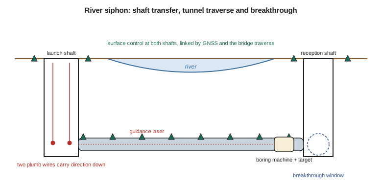
The siphon carries a 1.8 m (72 in) steel pipe under the Sun River, from a launch shaft on the north bank to a reception shaft on the south bank, a drive of 420 m (1,378 ft). It will be built by microtunnelling: a remotely controlled boring machine is jacked forward from the launch shaft, pushing a string of pipe sections behind it, while the operator steers from a control cabin on the surface using a laser guidance system. Mira, who brings marine and river experience, and Theo share the tunnel survey. Tunnel specifications for this job, like many, are written in metric units, and the numbers in this lesson are in meters and millimeters.
Surface control
Everything starts with surface control linking the two shafts. Because the river is between them, the crew cannot see from one shaft to the other at ground level, so the link is made by GNSS static sessions on monuments at each shaft, tied to the project network, and checked by a total-station traverse along the bridge and back, in Lesson 7's bridge control. The result is a pair of monuments at each shaft, with their coordinates and the azimuth between them known to a few arc-seconds. The design line of the siphon, from launch to reception, is defined in the same coordinates, with its grade.
The surface control near the shafts must be stable and protected. The launch shaft has heavy equipment around it for months, including the jacking frame, cranes and spoil handling; the monuments must be well outside the zone where ground settles as the shaft is excavated, and checked regularly against more distant control.
Transferring position and direction down a shaft
Position is easy to carry down a shaft: a plumb wire, an optical or laser plummet, or a total station looking straight down gives the plan position of a point at the bottom. Direction is the hard part. The shaft is only a few meters across, so any baseline that can be set up at the bottom is short, and a small error in its ends becomes a large error in direction. The classic method hangs two heavy plumb wires in the shaft, as far apart as the shaft allows, with their bobs damped in oil. The surface crew fixes their positions from the surface control; the tunnel crew measures to them from below, and the line between them gives the direction for the tunnel.
The weakness is the short base. With two wires 3.2 m apart, each placed or measured with an error of half a millimeter, the direction of the line between them has an error of about 45 arc-seconds, and that error swings the whole tunnel. Over 420 m, 45 arc-seconds is about 93 mm sideways at the far end. That is why tunnels rely on independent direction checks.
A gyro-theodolite, or gyrotheodolite, measures true north directly using a spinning gyroscope that settles toward the meridian under the Earth's rotation. Modern gyro instruments give azimuths to a few arc-seconds in a few minutes, independent of any wires or baselines, and they work underground. Measuring a gyro azimuth on the first tunnel leg, and again at intervals as the tunnel advances, removes the short-base problem. The gyro azimuth must be corrected from astronomic to grid, by the convergence of meridians and the small difference between astronomic and geodetic north, as GEOM-340 described.
The breakthrough budget
Before the drive starts, Theo estimates how far off the tunnel might be at breakthrough, the expected error budget. It combines the error of the surface control, the error in carrying direction down the shaft, and the errors that accumulate in the tunnel traverse. The lateral error is the critical one, because the boring machine must arrive within the reception shaft's opening, and the pipe must be within its alignment tolerance.
In an open traverse with n legs of length s, each with an angle error \(\sigma_a\), the angle errors accumulate: an error at the first station swings all the following legs, an error at the second swings all but the first, and so on. The lateral error at the end grows roughly with n to the power 1.5.
import math
# River siphon microtunnel: how big can the breakthrough error be? (lengths in m, angles in arc-seconds)
drive = 420.0                 # launch shaft to reception shaft
legs = 7                      # tunnel traverse legs of about 60 m
s = drive / legs
sig_a = 2.0                   # angle standard deviation per station, arc-seconds
sig_d = 0.002                 # distance standard deviation per leg, m
rho = 206265.0
# Orientation transferred down the 9 m launch shaft from two plumb wires 3.2 m apart
wire_base, sig_wire = 3.2, 0.0005             # wire separation and placement error of each wire, m
sig_orient = math.sqrt(2) * sig_wire / wire_base * rho   # arc-seconds
lat_orient = drive * sig_orient / rho
# Open (no-check) traverse: angle errors accumulate along the legs
k = sum(i * i for i in range(1, legs + 1))
lat_angles = s * sig_a / rho * math.sqrt(k)
lat_total = math.hypot(lat_orient, lat_angles)
print(f"orientation from the wires: {sig_orient:.1f}″ -> {1000*lat_orient:.1f} mm at the far shaft")
print(f"traverse angles: {1000*lat_angles:.1f} mm   combined lateral sigma {1000*lat_total:.1f} mm, 95 % {1000*1.96*lat_total:.0f} mm")
# A gyro azimuth (sigma 5 arc-seconds) on the first tunnel leg replaces the short-base wire orientation
sig_gyro = 5.0
lat_g = math.hypot(drive * sig_gyro / rho, lat_angles)
print(f"with a gyro azimuth on the first leg: lateral sigma {1000*lat_g:.1f} mm, 95 % {1000*1.96*lat_g:.0f} mm")
print(f"longitudinal sigma from distances: {1000*sig_d*math.sqrt(legs):.1f} mm")
# Line-and-grade check: laser target reading at 280 m vs design
design_off, read = 0.000, 0.017
print(f"target at 280 m reads {1000*read:.0f} mm right of line; tolerance 50 mm -> {'steer back gently' if abs(read) < 0.05 else 'stop and resurvey'}")orientation from the wires: 45.6″ -> 92.8 mm at the far shaft traverse angles: 6.9 mm combined lateral sigma 93.1 mm, 95 % 182 mm with a gyro azimuth on the first leg: lateral sigma 12.3 mm, 95 % 24 mm longitudinal sigma from distances: 5.3 mm target at 280 m reads 17 mm right of line; tolerance 50 mm -> steer back gently
The budget shows how much the method matters. With wire orientation alone, the lateral standard deviation at the reception shaft is 93 mm, dominated by the 45-arc-second direction error from the short wire base; the traverse angles add only 7 mm. At 95 % confidence the machine could be 18 cm off line. With a gyro azimuth on the first leg, the orientation error falls to 5 arc-seconds and the total lateral standard deviation to 12 mm, or 24 mm at 95 %. The specification allows 50 mm. The decision is easy: the job will use a gyro.
The longitudinal error, from the distance measurements, is about 5 mm, small because modern total stations measure distance very precisely; and the vertical error, from leveling carried down the shaft and along the tunnel, is usually smaller still. On longer tunnels, vertical control can be more demanding because the line must hold its grade for drainage, and the leveling is run carefully on every leg.
Guiding the machine
A microtunnel boring machine is guided by a laser set up in the launch shaft on the design line and grade, shining along the pipe onto an active target in the machine. The target shows the operator how far the machine's head is off the line and grade, and the operator steers with hydraulic jacks that tilt the cutting head. The surveyor's job is to set the laser on line and grade from the shaft control, to check it at the start of each shift and after any disturbance, and to run a traverse through the pipe at intervals to check the machine's true position, because the laser itself can drift if its mount moves or the shaft settles.
The last line of the code checks a target reading at 280 m: the machine is 17 mm right of line, within the 50 mm tolerance, so the operator steers gently back toward the line. Correcting too hard causes a kinked pipe and high jacking forces; the rule is small, steady corrections, watched by the surveyor and the operator together.
Laser beams in tunnels bend. Air near the tunnel walls is often warmer or cooler than the air in the middle, and temperature gradients refract the beam toward the denser, cooler air. On long drives the lateral refraction can be several centimeters, so laser guidance is always checked by traverse, and the traverse sights are kept away from walls and heat sources where possible.
Worked problem
Orientation from plumb wires
Two wires in a shaft are 4.0 m apart, and each is measured with an error of 0.4 mm. Estimate the direction error and the lateral error at 300 m.
Show solution
- \[\sigma_\alpha = \frac{\sqrt{2} \times 0.0004}{4.0} \times 206\,265 = 29.2''\]
- \[\sigma_{\text{lat}} = 300 \times \frac{29.2}{206\,265} = 0.042\ \text{m}\]
Answer: About 29 arc-seconds and 42 mm. A wider shaft helps, but a gyro azimuth helps more.
Traversing in a tunnel
Traverse stations in a small tunnel or pipe are usually brackets on the wall or crown, or forced-centering consoles, so that the instrument and targets can be set on exactly the same points each time. The sights are short, often 50 to 100 m, and every station is occupied with both faces and several sets. Where the tunnel is wide enough, a double traverse, two separate lines of stations along each side, gives an internal check: the two traverses must agree at each pair of stations. In a 1.8 m pipe, a double traverse is not possible, so the gyro checks and repeated runs of the traverse are the checks.
Conditions underground are hard on instruments and people. Air may be humid and dusty, lighting poor, and the pipe crowded with cables, hoses and slurry lines. Ruth's rule is to repeat the traverse completely at least three times during the drive, independently, and to compare each run with the previous ones; a station that moves between runs is replaced.
Breakthrough and as-built
When the machine arrives at the reception shaft, the crew measures its actual position relative to the shaft control. The difference between the predicted and actual position is the breakthrough error, and it tells everyone how good the survey was. The traverse is then closed through the reception shaft, which gives a closed traverse for the first time, and the as-built position of the pipe is computed at each joint. The as-built report of Lesson 11 uses those positions to check the pipe's line and grade.
Safety governs every step underground. Shafts and tunnels are confined spaces with hazards from atmosphere, falling objects and moving equipment. OSHA's rules for underground construction in 29 CFR 1926 Subpart S and for confined spaces in construction apply, and surveyors entering the shaft or the pipe must be trained, follow the entry permit, carry gas monitors, and be covered by the contractor's rescue plan. Microtunnelling reduces entry, because no one needs to be at the face, but the survey still requires entries to the pipe for traverse runs.
Settlement above the drive
Tunneling disturbs the ground above it. Even a small microtunnel can cause settlement at the surface if the face pressure is too low or the annular gap around the pipe is not filled with lubricant and grout. The siphon passes under the river and its banks, and under the access road to the headworks, so the monitoring of Lesson 9 extends to a line of settlement points along the drive on each bank. The crew levels them before the machine arrives, daily while it passes, and weekly afterwards until movement stops. A settlement trough a few millimeters deep is normal; a sudden drop of a centimeter over the machine is a sign of overexcavation, and the operator and the engineer must be told at once so that the face pressure can be adjusted.
The river itself needs watching too. A drive under a river bed with too little cover can lose its slurry into the river, or let river water into the face. The hydrographic survey of the bed (Lesson 1 and GEOM-360) gave the cover along the drive, and the designers kept it above the minimum the geotechnical engineer set. During the drive, the crew repeats a few echo-sounder lines over the alignment to check that the bed has not scoured since the design survey.
Common mistakes
MistakeRelying only on a short wire base for tunnel direction.
InsteadAdd independent gyro azimuths as the tunnel advances.
MistakeTrusting the guidance laser without traverse checks.
InsteadCheck the machine's position by traverse at intervals.
MistakeSteering hard to correct a small offset.
InsteadMake small, steady corrections to avoid kinks and high jacking loads.
MistakeRunning the tunnel traverse once.
InsteadRepeat it independently and compare runs.
Summary and key terms
- Tunnel surveys must carry position and direction underground and extend them without a closed check until breakthrough.
- Direction transfer down a shaft is weak because the base is short; gyro azimuths fix this.
- Lateral error in an open traverse grows roughly with the 1.5 power of the number of legs.
- A breakthrough budget combines surface, transfer and traverse errors before the drive starts.
- Laser guidance steers the machine; repeated traverses check the laser and the machine.
- Shafts and tunnels are confined spaces with strict entry rules.
- Microtunnelling
- Remotely controlled pipe jacking with a guided boring machine.
- Launch and reception shafts
- The shafts where a drive starts and finishes.
- Plumb wires
- Weighted wires hung in a shaft to transfer position and direction down.
- Gyrotheodolite
- An instrument that measures true north using a gyroscope.
- Breakthrough error
- The difference between the predicted and actual position at the end of a drive.
- Forced centering
- Mounting instruments and targets on fixed bases so they occupy exactly the same points.
- Lateral refraction
- Sideways bending of a line of sight by temperature gradients near walls.
Practice problems
Work each problem on paper first, then reveal the answer to check.
Wires 5.0 m apart are each placed to 0.5 mm. What is the direction error?
Show answer
√2 × 0.0005/5.0 × 206,265 = 29.2 arc-seconds.
What is the lateral error at 500 m from a 10 arc-second direction error?
Show answer
500 × 10/206,265 = 0.024 m.
Why does lateral error in an open traverse grow faster than the number of legs?
Show answer
Each angle error swings every following leg.
What corrections must be applied to a gyro azimuth before use?
Show answer
From astronomic to geodetic north and from geodetic to grid by the convergence.
Why is a double traverse useful in a large tunnel?
Show answer
The two independent lines check each other at every pair of stations.
Lesson quiz · 5 questions
Score 60% or more to complete this lesson.
Create a free account to save your progress, take quizzes and earn a certificate.