
GEOM-420 · Lesson 5 of 12 · 21 min
Construction layout
Construction layout, or staking, puts the design on the ground so that the builders can build it in the right place, at the right height and in the right shape. It is the most visible part of engineering surveying and the part with the least room for error, because concrete, steel and pipe do not move once they are placed. A layout crew must work fast, because equipment and workers are waiting, and work right, because a mistake can cost far more than the survey. This lesson covers the methods, the marks, the checks and the habits that make layout reliable, using the pump station as the example.
From design to layout data
Layout starts in the office. Theo receives the design drawings and the digital design model, checks that they agree with each other and with the control, and prepares layout data: coordinates and elevations for every point to be staked, with a description of what each point is and what the crew should mark. For the pump station that means the building corners, column centers, the pump bases and their anchor-bolt groups, the wet well, the inlet and discharge pipe connections, and the floor and footing elevations.
The check of the design is a large part of the job. Theo computes the building's dimensions from the design coordinates and compares them with the dimensions on the architectural and structural drawings; he checks that the column grid is square, that the floor elevation agrees across drawings, and that the pipe inverts match the civil profile. Discrepancies are sent to the engineer as written questions, and nothing is staked until they are answered. A building staked exactly as one drawing says, when another drawing says something different, is not a correct layout.
Methods of layout
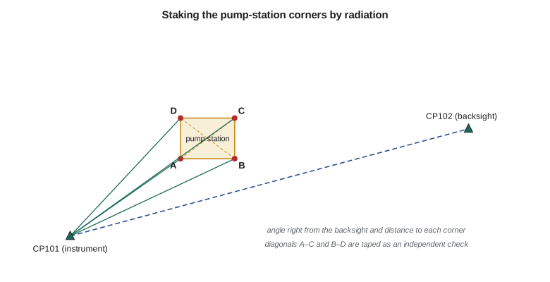
Most layout today is done by radiation from control. The instrument is set up on a known control point, oriented by sighting another, and each design point is set out by turning the computed angle and measuring the computed distance, with the instrument's software guiding the person holding the prism until the point is found. RTK GNSS does the same thing without line of sight, guiding the rover to each point's coordinates. Both are coordinate methods: every point is set independently from control.
Older methods still have their place. Offsets from a baseline, measured with tape and right angles, are quick for small buildings and for checking. Intersection, setting a point by angles from two control points, is useful where distances cannot be measured. Building lines and batter boards, a pair of posts with a cross board outside each corner of a building, carry the lines and the elevation past the excavation, so that strings can be stretched between them when the footings are formed. Whatever the method, the result should be checked by another method or from another control point.
The pump-station corners
The pump station is a rectangle 78.74 ft by 59.06 ft on the ground, with corners A to D. The nearest control points are CP101 and CP102, from Lesson 1's secondary control. The design coordinates are in state plane grid, in international feet, so the distances must be converted to ground with the combined factor of 0.999299 before they are measured.
import math
# Laying out the pump-station corners by radiation from control (grid coordinates, international feet)
CP = {'CP101': (16444.71, 10512.20), 'CP102': (17023.96, 10668.18)}   # (E, N), ft
k_comb = 0.999299             # combined factor at the site (Lesson 1): grid = ground x k
corners = {'A': (16605.15, 10624.67), 'B': (16683.89, 10624.67),
           'C': (16683.89, 10683.73), 'D': (16605.15, 10683.73)}
def inv(p, q):
    dE, dN = q[0] - p[0], q[1] - p[1]
    return math.degrees(math.atan2(dE, dN)) % 360, math.hypot(dE, dN)
def dms(a):
    d = int(a); m = int((a - d) * 60); s = (a - d - m / 60) * 3600
    return f"{d:3d}° {m:02d}′ {s:04.1f}″"
occ, bs = CP['CP101'], CP['CP102']
az_bs, d_bs = inv(occ, bs)
print(f"set up on CP101, backsight CP102: azimuth {dms(az_bs)}, grid {d_bs:.2f} ft, ground {d_bs/k_comb:.2f} ft")
print("point   angle right      grid dist   ground dist")
for n, p in corners.items():
    az, d = inv(occ, p)
    print(f"  {n}   {dms((az - az_bs) % 360)}   {d:9.2f}   {d / k_comb:9.2f}")
dAC = math.dist(corners['A'], corners['C']); dBD = math.dist(corners['B'], corners['D'])
print(f"diagonals A-C {dAC:.2f}, B-D {dBD:.2f} (grid); stake both and tape them on the ground")
# Cut or fill on an offset stake: design floor 3313.65, rod reading 5.52 from HI 3319.76
HI, rod, design = 3319.76, 5.52, 3313.65
ground = HI - rod
print(f"ground at stake {ground:.2f}; {'cut' if ground > design else 'fill'} {abs(ground - design):.2f} ft to design")set up on CP101, backsight CP102: azimuth 74° 55′ 44.1″, grid 599.88 ft, ground 600.30 ft point angle right grid dist ground dist A 340° 02′ 24.9″ 195.93 196.07 B 349° 53′ 12.1″ 264.30 264.49 C 339° 25′ 28.4″ 294.33 294.54 D 328° 09′ 27.8″ 234.87 235.03 diagonals A-C 98.43, B-D 98.43 (grid); stake both and tape them on the ground ground at stake 3314.24; cut 0.59 ft to design
From CP101, backsighting CP102, the angles to the corners run from 328° to 350° to the right, and the ground distances from 196.07 ft to 294.54 ft. The ground distances are about 0.14 to 0.21 ft longer than the grid distances: a large error if ignored, many times the tolerance for anchor bolts. The building's diagonals should each be 98.43 ft in grid and 98.50 ft on the ground; after staking, the crew tapes both diagonals and both widths as a check that is independent of the instrument. The offset stake at the last line reads a ground elevation of 3,314.24, so the excavation must cut 0.59 ft to reach the design floor of 3,313.65.
Offset stakes, hubs and marks
Points set exactly where something will be built do not survive long: the excavator digs them out. So the crew sets offset stakes, a fixed distance outside the work, usually on two lines through each corner, so that the corner can be re-created at any time by stretching lines between them. Each offset stake is a hub, a solid wooden or steel stake driven flush with a tack or punch mark, with a guard lath beside it carrying the information: the point it refers to, the offset distance and direction, and the cut or fill to a stated elevation.
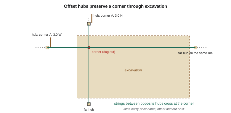
Color and lettering conventions vary by agency and contractor, and the crew follows the project's: commonly a hub with a tack for line, a lath with the information, and flagging of an agreed color for each kind of point. Ruth's crews write the information on the lath in a standard order and print the same information in a daily stake report, so that a superintendent who finds a disturbed stake can tell the surveyor exactly which one.
Heights and grades
Elevations on a building site are set from the project benchmarks by leveling, or by total station with a careful height of instrument. The crew sets a temporary benchmark near each structure, checked from two permanent ones, and uses it for footing, floor and anchor-bolt elevations. Cut and fill are marked as the difference between the stake or reference mark and the design elevation, as in Lesson 3. For floors, the crew may instead mark the design elevation directly on a nearby wall or post, a line the trades can measure from with a tape.
Grades for pipes and channels are carried by grade boards or lasers. For the pump station's inlet pipe, the crew sets the pipe laser at the first joint, aligned on the pipe's line and set to its grade, and checks it at the start of each shift from the offset hubs. Lesson 11 covers the as-built check that follows.
Layout tolerances
Every item has a tolerance, and the crew must know it before staking. Earthwork stakes might be good enough to a few centimeters; building corners to a few millimeters; anchor bolts for machinery to two or three millimeters relative to each other; the pump bases in Lesson 11 to 6 mm. The tolerance tells the crew how to work: which instrument, how many checks, whether a GNSS position is good enough or a total station is needed, and whether to shoot each point twice. A layout that is more precise than needed wastes time; one that is less precise than needed is a defect.
The relevant standards set out how to set and check points for buildings. ISO 4463, on setting-out for building construction, describes methods and permitted deviations for different kinds of work, and the steel and concrete tolerance standards published by AISC and ACI give construction tolerances that the layout must support. The project's specifications say which apply.
Checks, always
The golden rule of layout is that every point is checked by a measurement that would reveal an error in the first one. Checks can be: staking from a second control point; measuring distances between staked points and comparing them with the design; shooting a staked point back with the same instrument but a different setup; or, for GNSS, re-occupying the point after the satellite geometry has changed. The diagonals of a rectangle are the classic check, because a building that is out of square has unequal diagonals even if each side is the right length.
The instrument setup itself needs checks. After orienting on the backsight, the crew measures the distance to the backsight and compares it with the computed distance, and shoots a third control point as a check. At the end of each setup, it re-sights the backsight to confirm the instrument has not moved. A setup error affects every point set from that setup, so it is the most important error to catch.
Worked problem
Setting a point by radiation
An instrument on P (E 3000.00, N 6000.00) backsights Q (E 3300.00, N 6000.00). Point S is at E 3150.00, N 6150.00. Find the angle right from Q to S and the grid distance.
Show solution
- \[\alpha_{PQ} = 90^\circ \qquad \alpha_{PS} = \operatorname{atan2}(150, 150) = 45^\circ\]
- \[\theta = 45^\circ - 90^\circ + 360^\circ = 315^\circ\]
- \[d = \sqrt{150^2 + 150^2} = 212.13\ \text{ft}\]
Answer: Turn 315° to the right from Q (or 45° to the left) and measure the distance, converted to ground if the coordinates are grid.
Working safely on an active site
A construction site is a moving, noisy place, and survey crews are often the only people on foot among heavy machines. Every crew member takes the contractor's site orientation, wears the required protective equipment, makes eye contact with operators before entering their area, and never stands in the swing radius of an excavator or behind a reversing truck. Stakes near excavations are set and read from outside the protective zone, as Lesson 4 noted. Ruth's crews hold a short safety talk at the start of each day, using the hazard assessment the site requires, and stop work if conditions change.
Daily layout routine
A layout day on a busy site follows a pattern. The crew lead meets the superintendent first thing to agree on the day's priorities: which footings are being formed, which pipes are going in, what the machines need. The crew loads the day's layout file, checks it against the latest drawing revision, and sets up on control with the usual backsight and check shots. It stakes the priority items first, checks them, and writes them up in the stake report before moving on. At the end of the day, it re-checks any control used, downloads the raw data, and sends the stake report to the superintendent and to Theo, who archives the data and updates the record of which points have been set.
Revision control is the hidden danger in this routine. Drawings change during construction, and a layout file built from last week's revision may stake something that has since moved. The project's rule is that every layout file carries the drawing numbers and revisions it was built from, and the crew lead confirms with the superintendent each morning that those are still current. When a new revision arrives, Theo compares it with the previous one and flags every changed point, and the crew re-stakes any affected points that are already on the ground.
Communication with the trades is the last part of the routine. A carpenter forming a footing, a pipe layer setting a laser and an ironworker placing anchor bolts each need to understand the marks the surveyor left. Ruth's crews walk the foreman through any unusual marks, especially offsets in an unexpected direction or elevations referred to something other than finished floor, and they never leave a mark that only the surveyor can read.
Common mistakes
MistakeStaking grid distances on the ground without the combined factor.
InsteadConvert grid to ground (or use a project datum) before measuring.
MistakeStaking straight from drawings without checking them.
InsteadCheck dimensions, squareness and elevations across drawings first.
MistakeSetting points without an independent check.
InsteadCheck each point from another control point, by tape, or by re-measurement.
MistakeSetting points where the excavation will destroy them.
InsteadUse offset hubs outside the work, on two lines through each point.
Summary and key terms
- Layout data are prepared and checked in the office before any staking.
- Radiation from control, by total station or GNSS, sets each point independently.
- Grid distances must be converted to ground for measuring on site.
- Offset hubs with guard laths preserve points through excavation.
- Tolerances decide the method, the instrument and the number of checks.
- Every point and every setup is checked by an independent measurement.
- Layout data
- Coordinates, elevations and descriptions of the points to be staked.
- Radiation
- Setting points by angle and distance from a single occupied control point.
- Offset stake
- A stake set a known distance outside the work so a point can be re-created.
- Hub
- A stake driven flush with a precise mark on its top.
- Guard lath
- A tall stake beside a hub carrying the point information.
- Batter board
- A board on posts outside a corner carrying lines and elevation past the excavation.
- Temporary benchmark
- A height reference set near a structure for the work there.
Practice problems
Work each problem on paper first, then reveal the answer to check.
Why are the diagonals of a rectangular building checked?
Show answer
Unequal diagonals reveal that the building is out of square even if the sides are right.
A grid distance is 150.00 ft and the combined factor is 0.999299. What ground distance is staked?
Show answer
150.00 / 0.999299 = 150.11 ft.
Give two ways to check a setup before staking.
Show answer
Measure the backsight distance and compare it, and shoot a third control point.
Why are offset hubs set on two lines through a corner?
Show answer
Strings between them re-create both lines and their intersection, the corner.
Who resolves a dimension that differs between two drawings?
Show answer
The engineer, in writing, before the point is staked.
Lesson quiz · 5 questions
Score 60% or more to complete this lesson.
Create a free account to save your progress, take quizzes and earn a certificate.