
GEOM-420 · Lesson 7 of 12 · 21 min
Bridge and building layout
Bridges and buildings are where layout is most demanding. A bridge's girders are fabricated in a shop to the millimeter, trucked to site, and lifted onto bearings that the survey crew set months earlier on piers it laid out before that; if the bearings are in the wrong place, the girders do not fit. A building's steel frame bolts onto anchor bolts cast in concrete footings, and its columns must stand plumb over many stories. This lesson covers the control, the computations and the checks for the canal bridge and for the pump station's structure, from the first pier stake to the final bearing elevations.
Control for structures
Structure layout starts with dedicated control. For the canal bridge, the crew sets four pillars or deep monuments, two on each bank of the canal, outside the excavation and away from the crane's working area, with a clear view of each other and of every pier and abutment location. The four are measured as a small network by repeated angles and distances, and adjusted by least squares (GEOM-220), so that their relative positions are known to a millimeter or two. The network is tied to the project control, but its internal precision is what matters for the bridge: the girders care about the spacing between the bearings, not about the bridge's position in the national frame.
The canal itself complicates the work. The crew cannot tape across it, so distances come from the total station; lines of sight run low over the water, where heat shimmer and refraction can affect angles in summer; and the water level changes with the district's operations. Ruth schedules the precise work for early morning, when shimmer is least, and observes in both faces with repeated sets.
The geometry of a skewed bridge
A bridge that crosses its obstacle at right angles has piers square to the roadway. Most crossings are skewed: the canal crosses under the highway at an angle, so the piers and abutments run parallel to the canal, not square to the road. The skew angle is the angle between the pier line and the line perpendicular to the roadway. Skew changes many things: the bearings on a pier line are offset along the line, the girders still run parallel to the road, and the distance between bearing points measured square to the road is shorter than the spacing along the pier.
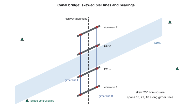
The canal bridge is a three-span structure on the straight part of the highway alignment, with spans of 59.06, 72.18 and 59.06 ft (18, 22 and 18 m) along the alignment and a skew of 25°. The design was done in meters by the bridge consultant, as many bridge designs now are, and the coordinates are delivered in both units; the survey works in the state plane feet the highway uses. Each line has a left and right bearing 17.72 ft (5.400 m) either side of the alignment, measured along the skewed line.
Here u is the unit vector along the alignment, n the unit vector square to it, β the skew angle, s the distance along the alignment and w the half-spacing of the bearings along the pier line. The code computes every bearing point this way and then checks the spans along each girder line and the bearing spacing.
import math
# Canal bridge: pier and bearing layout on a skewed crossing
U, u = {'ca': (1.0, 'm'), 'us': (1 / 0.3048, 'ft')}['us']
# Highway alignment through the bridge (straight), defined by two points (E, N); computed in m, printed in site units
P1 = (5200.000, 3100.000); P2 = (5260.000, 3290.000)
L = math.dist(P1, P2); ue = ((P2[0] - P1[0]) / L, (P2[1] - P1[1]) / L)
az = math.degrees(math.atan2(ue[0], ue[1])) % 360
skew = math.radians(25.0)                         # pier lines are skewed 25 degrees from square
spans = [0.0, 18.000, 40.000, 58.000]             # abutment 1, pier 1, pier 2, abutment 2 (along the alignment)
start = 62.000                                    # distance from P1 to abutment 1 bearing line
# Unit vector along a pier line: rotate the square-to-alignment direction by the skew
sq = (ue[1], -ue[0])                              # perpendicular, to the right
pl = (sq[0] * math.cos(skew) + ue[0] * math.sin(skew), sq[1] * math.cos(skew) + ue[1] * math.sin(skew))
print(f"alignment azimuth {az:.4f}°")
pts = {}
for i, s in enumerate(spans):
    c = (P1[0] + ue[0] * (start + s), P1[1] + ue[1] * (start + s))
    for side, off in (('L', -5.400), ('R', 5.400)):       # bearings 5.4 m each side, measured along the pier line
        pts[f"{i}{side}"] = (c[0] + pl[0] * off, c[1] + pl[1] * off)
    print(f"line {i}: middle E {c[0]*U:.3f} N {c[1]*U:.3f}  bearings L {pts[f'{i}L'][0]*U:.3f},{pts[f'{i}L'][1]*U:.3f}  R {pts[f'{i}R'][0]*U:.3f},{pts[f'{i}R'][1]*U:.3f}")
# Checks the crew will tape or measure: span between bearing points on the same girder line
for side in 'LR':
    d = [math.dist(pts[f'{i}{side}'], pts[f'{i+1}{side}']) for i in range(3)]
    print(f"girder line {side}: spans " + ", ".join(f"{x*U:.3f}" for x in d) + f" {u}")
w = math.dist(pts['1L'], pts['1R'])
print(f"bearing spacing along the skewed pier line {w*U:.3f} {u}; square to the alignment {w*math.cos(skew)*U:.3f} {u}")alignment azimuth 17.5256° line 0: middle E 17121.621 N 10364.574 bearings L 17104.055,10362.269 R 17139.187,10366.879 line 1: middle E 17139.405 N 10420.888 bearings L 17121.839,10418.583 R 17156.971,10423.192 line 2: middle E 17161.140 N 10489.716 bearings L 17143.574,10487.411 R 17178.706,10492.021 line 3: middle E 17178.923 N 10546.030 bearings L 17161.357,10543.725 R 17196.489,10548.335 girder line L: spans 59.055, 72.178, 59.055 ft girder line R: spans 59.055, 72.178, 59.055 ft bearing spacing along the skewed pier line 35.433 ft; square to the alignment 32.113 ft
The alignment azimuth is 17.5256°, and the four bearing lines have centers from E 17,121.621, N 10,364.574 ft onward. The spans along both girder lines are exactly 59.055, 72.178 and 59.055 ft, as they should be, because the bearing lines are parallel. The bearing spacing along a pier line is 35.433 ft, but measured square to the alignment it is only 32.113 ft. A crew that taped 35.43 ft square across the deck would put the girders over 3 ft too far apart. That is the kind of error the computation prevents, and the kind the field check catches.
Staking piers and abutments
Pier construction goes in stages, and each stage needs layout. First the excavation or pile locations: the bridge sits on piles in the canal banks, and each pile is staked by coordinates from the bridge control, with offset stakes for the pile-driving crew. After driving, the crew measures each pile's actual position and the engineer checks it against the tolerance; a pile driven off position may need a design change in the cap. Then the pile cap or footing forms, then the pier column or wall, and finally the bearing seats. At each stage, the layout is set from the bridge control and checked by measuring between finished elements: the distance from one pier to the next, the skew, the elevation of each seat.
Elevations on a bridge are critical because the girders have a fixed depth and camber, and the deck must meet the profile of Lesson 3 at each end. The bearing seat elevation at each bearing comes from the profile elevation at that point minus the deck thickness, the haunch, the girder depth and the bearing height, and it varies along a skewed pier line because each bearing is at a different station and offset. The crew sets the seat elevations from a benchmark checked on both banks, by leveling across the canal with reciprocal observations if the distance is long, so that refraction errors cancel.
Worked problem
Bearing spacing on a skew
Two bearings on a pier line are 40.00 ft apart along the line, and the skew is 30°. How far apart are the girder lines, measured square to the alignment?
Show solution
- \[40.00\cos 30^\circ = 34.64\ \text{ft}\]
Answer: The square spacing is the skewed spacing times the cosine of the skew.
Building structures
The pump station's structure is a concrete substructure, with the wet well and pump bases below grade, and a steel frame above. The building grid, the lines on which the columns sit, is the reference for everything. Theo computes the grid lines from the corners staked in Lesson 5, and the crew sets offset monuments for each grid line outside the building, on the slab edges or on posts, so that the lines can be re-established at any time.
Anchor bolts are the most exacting part. Each steel column sits on a base plate with four or more bolts, and the bolts must be within a few millimeters of their design positions relative to each other, and within a slightly larger tolerance relative to the grid. The crew sets the bolt groups with templates, plywood or steel plates drilled to the bolt pattern, positioned by total station before the concrete is placed, and checks them again after the pour, because concrete placement can push templates out of position. A bolt group out of tolerance must be reported to the engineer before the steel arrives, not after.
Plumb and vertical transfer
Columns, walls and lift shafts must be plumb. On a single-story pump station, a total station checking the top and bottom of each column against the grid is enough. On taller buildings, the grid is transferred up through openings in each floor slab with an optical plummet or laser plummet set over a reference point on the ground floor, and the crew rebuilds the grid on each floor from those transferred points, rather than from the floor below. Each floor's grid is checked by measuring between the transferred points, and any error is caught before it is built in.
Heights are transferred up the same way, by measuring with a steel tape or a total station from a benchmark at the base. Steel tapes need corrections for temperature and tension on long hangs, and the total station needs a known instrument height. Either way, the height on each floor is set from the base, not from the floor below, so that errors do not accumulate.
Thermal and other movements
Structures move. Steel girders lengthen by about 12 parts per million per degree; a 22 m span changes length by about 8 mm between a cold winter morning and a hot summer afternoon on the coulee. Concrete also expands, and it shrinks and creeps as it cures. The bridge's design specifies the bearing positions at a reference temperature, and the crew sets them for the temperature on the day, using the engineer's table. Ruth's crew records the air and steel temperatures with every precise measurement on the structure.
Measurement instruments and the survey targets themselves are affected too. Prisms mounted on new concrete can move as the concrete cures; benchmarks on a slab can sink as the slab settles. The crew keeps its primary references off the structure and treats any reference on the structure as temporary.
Documentation for structures
Every structural layout is recorded: the coordinates and elevations set, the date and temperature, the instrument and the control used, and the check measurements with their results. For the bridge, the crew prepares a pier and bearing report after each stage, with measured versus design positions and elevations, which the engineer signs before the next stage begins. Those reports become part of the as-built record of Lesson 11 and are the basis for resolving any dispute about fit when the girders arrive.
Working around a bridge site brings particular hazards. Work near and over water needs fall protection and, where required, flotation devices and a rescue plan; working under suspended loads is never allowed; and the crane's exclusion zone is respected even if it means a longer setup. The crew's daily hazard assessment covers these before work starts.
Camber, deflection and the deck profile
Girders are not straight. They are fabricated with camber, an upward curve that will be taken out by their own weight, the deck and the long-term effects of creep, so that the finished deck follows the design profile. The bridge engineer gives the camber and the expected deflections at each tenth of each span, and the surveyor uses them to set the deck forms or screed rails: the form elevation at each point is the design profile plus the deflection still to come when the deck is poured. After the pour, the crew surveys the deck and compares it with the profile, and any difference is reported to the engineer. Getting this right is what makes a bridge feel smooth to drive over.
Common mistakes
MistakeTaping bearing spacing square across a skewed bridge.
InsteadSquare spacing equals skewed spacing times the cosine of the skew.
MistakeSetting each floor's grid from the floor below.
InsteadTransfer the grid and heights from the base on every floor.
MistakeChecking anchor bolts only before the pour.
InsteadCheck again after the pour, before the steel arrives.
MistakeIgnoring temperature when setting bearings.
InsteadSet positions for the day's temperature from the engineer's table and record it.
Summary and key terms
- Structures need dedicated, precise control with good geometry and clear sightlines.
- Skew changes bearing positions and spacing; computations must use the skewed geometry.
- Each construction stage is laid out from control and checked between finished elements.
- Anchor bolts and bearing seats are the tightest tolerances on most jobs.
- Vertical transfer of grids and heights is from the base on every floor.
- Thermal movement and curing affect both the structure and the targets on it.
- Skew angle
- The angle between a pier line and the line square to the roadway.
- Bearing seat
- The prepared surface on a pier or abutment on which a bearing sits.
- Building grid
- The set of reference lines on which a building's columns and walls are located.
- Anchor bolt template
- A plate drilled to a bolt pattern, used to hold bolts in position during a pour.
- Optical plummet
- An instrument that projects a vertical line of sight to transfer points up a building.
- Reciprocal leveling
- Leveling from both ends of a long sight so that refraction and curvature errors cancel.
- Coefficient of thermal expansion
- The change in length per unit length per degree of temperature.
Practice problems
Work each problem on paper first, then reveal the answer to check.
Bearing spacing along a pier line is 30.00 ft with a skew of 20°. What is the square spacing?
Show answer
30.00 cos 20° = 28.19 ft.
Why are bridge control pillars set outside the crane's working area?
Show answer
So they are not disturbed and remain visible throughout construction.
How much does a 40 m steel girder change length over 25 degrees?
Show answer
12 × 10⁻⁶ × 40,000 mm × 25 = 12 mm.
Why is reciprocal leveling used across the canal?
Show answer
Refraction and curvature errors on the long sight cancel.
When should an out-of-tolerance anchor bolt group be reported?
Show answer
As soon as it is found, before the steel arrives.
Lesson quiz · 5 questions
Score 60% or more to complete this lesson.
Create a free account to save your progress, take quizzes and earn a certificate.