
GAS-130 · Lesson 9 of 12 · 23 min
Reading ladder and wiring diagrams
▶ Video coming soon A video version of this lesson is on the way.
On the inside of every furnace door, and on the back of every boiler's jacket panel, there is a sheet of paper that tells you how the appliance is wired. Most homeowners never see it; some technicians never read it. On a slow afternoon in the second week of November, Hank Morrow sat Jonah down at the shop table with three diagrams: one from the Fairhaven furnace, one from an older furnace with a separate fan center, and one from the gas-fired rooftop unit at the Eastgate plaza. "Every one of these is two drawings," Hank said. "One shows you where the wires go. The other shows you what they do. Learn to read the second one and you can work on equipment you've never seen. Learn to read the first one and you can find the wire you're looking for."
This lesson explains the two kinds of diagram found on gas appliances, the wiring diagram and the ladder diagram, the symbols and conventions they use, and how to read a ladder diagram to understand what happens, rung by rung, when the appliance runs. It uses a simplified practice furnace diagram, not any manufacturer's, and leaves the detailed sequences of modern controls to the later course on appliance controls.
Two kinds of diagram
A wiring diagram, also called a connection or pictorial diagram, shows components roughly where they sit in the cabinet, with each wire drawn from terminal to terminal, usually with its color and gauge marked. It answers the question where: where is the pressure switch, which terminal does the orange wire go to, which plug on the board does the inducer connect to. It is the drawing to use when replacing a part or tracing a wire.
A ladder diagram, also called a schematic, line or elementary diagram, ignores physical layout and draws each circuit in the simplest possible way, so that its function is easy to see. It answers the question what: what has to be closed for the gas valve to open, what does the door switch interrupt, what turns the blower on. It is the drawing to use when troubleshooting. Many appliances print both on the same sheet, the ladder on one side and the wiring diagram on the other, with the same component labels on both.
How a ladder diagram is drawn
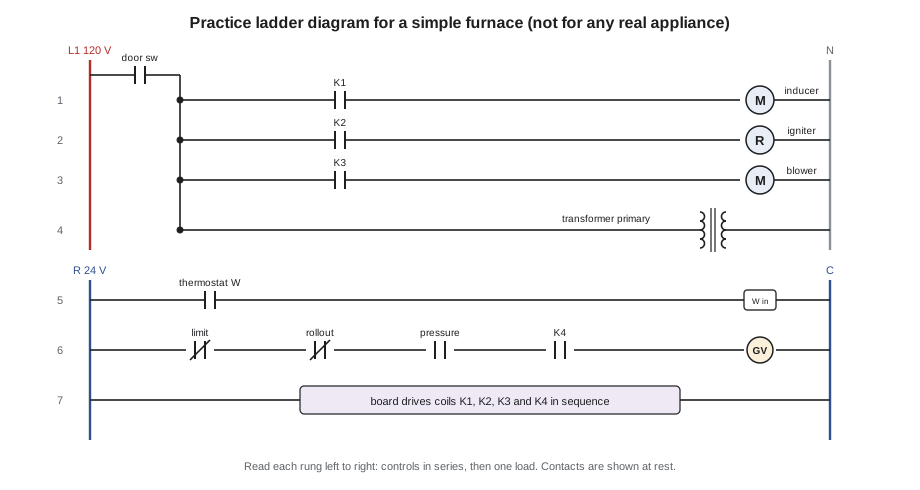
A ladder diagram looks like a ladder standing on end. The two vertical rails are the supply: on the line-voltage part of the diagram, the hot conductor, often marked L1, on the left and the neutral, N, on the right; on the low-voltage part, the transformer's R side on the left and C on the right. Between the rails, each horizontal rung is one circuit. Reading a rung from left to right, you meet first the switches and contacts that control it, in series, and then, at the right-hand end, the load it powers: a motor, a coil, an igniter or a lamp. As a rule, each rung has one load, and loads are not wired in series with each other.
A ladder diagram is read top to bottom and left to right, in the order things tend to happen. The transformer usually appears where the line-voltage section and the low-voltage section meet, with its primary across the line-voltage rails and its secondary feeding the low-voltage rails. Rungs are often numbered down the left side so that a component can be found by its rung number.
Symbols and labels
Diagrams use standard symbols, though manufacturers vary in the details, and every diagram has a legend that explains its own. Learn the common ones and always check the legend. Contacts are drawn as two short parallel lines, open for normally open and with a diagonal slash across for normally closed. A relay coil is usually a circle or a rectangle, labeled with the relay's name, such as K1 or IR for inducer relay. The contacts of that relay appear elsewhere on the diagram, often on a different rung, with the same label. That shared label is the key to reading relay logic: when coil K1 is energized, every contact labeled K1, wherever it appears, changes from its normal position.
Temperature switches are drawn as a contact with a small symbol for temperature, often a zig-zag or a curved line, and pressure switches with a symbol for a diaphragm. Motors are circles with an M or a symbol for the motor type, with their capacitors drawn as two parallel lines, one of them curved. Transformers are two coils side by side. Fuses are small rectangles or an S-shaped line. Ground connections are a set of shortening horizontal lines. Wires that cross without connecting are drawn crossing plainly or with a small hump; wires that connect have a dot at the junction.
Line styles carry meaning too. Solid lines are usually factory wiring; dashed lines are usually field wiring, the connections the installer makes, such as the supply, the thermostat and the outdoor unit. Line-voltage and low-voltage wiring are sometimes drawn with different weights. And contacts are always drawn in their normal position, as lesson 6 explained: switches at rest, relay coils not energized, the appliance off.
| Symbol or convention | Meaning |
|---|---|
| Two parallel lines | Normally open contact |
| Two parallel lines with a slash | Normally closed contact |
| Circle or rectangle labeled K1, CR or similar | Relay coil; contacts with the same label belong to it |
| Circle with M | Motor |
| Two coils side by side | Transformer |
| Dot at a junction | Wires connected |
| Lines crossing without a dot | Wires not connected |
| Dashed line | Field wiring, made by the installer |
| Shortening horizontal lines | Ground connection |
Reading a rung
To read any rung, ask two questions. What does this rung power? Look at the right-hand end. What has to happen for it to be powered? Look at every contact to its left: all of them must be closed at the same moment for current to reach the load. If one is a relay contact, find that relay's coil on another rung and ask what powers it. If one is a safety switch, ask what condition closes it. Following that chain backwards, from the load that is not working toward the supply, is how a ladder diagram turns a fault into a short list of suspects.
Worked problem
What must close for the gas valve to open?
On the practice ladder diagram, the gas valve coil is on rung 6. Reading left to right, the rung has the high-limit switch, the rollout switch, the pressure switch, and the board's gas valve contact K4, all in series with the coil between R and C. List everything that must be true for the gas valve to be energized, and find the voltage across the coil when it is, if the transformer delivers 25 V and each closed contact drops 0.1 V.
Show solution
- Every series contact must be closed: the limit (not overheated), the rollout switch (no rollout), the pressure switch (inducer proving draft) and K4 (board has completed its ignition checks).
- Add the drops across the four closed contacts:
- \[4 \times 0.1 = 0.4 \text{ V}\]
- Subtract from the supply:
- \[V_{\text{coil}} = 25 - 0.4 = 24.6 \text{ V}\]
Answer: The gas valve sees 24.6 V, well within its range. If it did not open with those readings, the coil or the valve itself would be suspect; if the coil had zero volts, the open would be in one of the four contacts, found by measuring across each.
Reading a sequence
Once each rung makes sense on its own, the diagram can be read as a sequence: the order in which rungs are energized during a cycle. On the practice furnace, a heat call puts 24 volts on the board's W input. The board energizes K1, closing the inducer contact on rung 1, and the inducer runs. Air movement closes the pressure switch on rung 6. The board, sensing that the pressure switch has closed, energizes K2, and the igniter on rung 2 heats. After the igniter's warm-up time, the board closes K4, and with the limit, rollout and pressure switches closed, the gas valve opens. After a delay, K3 closes and the blower on rung 3 runs. When the call ends, the board opens K4, the gas valve closes, and after the post-purge and blower-off delays it de-energizes K1 and K3.
Real control boards add many checks to this sequence: proving that the pressure switch is open before the inducer starts, sensing flame after the gas valve opens, counting failed trials and locking out, and reporting faults with flashing lights or codes. Those details belong to the course on appliance controls. What matters here is the method: identify the rungs, find what powers each one, and follow the order in which they come on. A technician who can do that can predict what should be happening at any moment and compare it with what is.
Using the wiring diagram
When the ladder diagram has shown which component is suspect, the wiring diagram shows where to find it and which wires to measure. It shows connector plugs and their pin numbers, wire colors, and the order of components along a harness. On the practice furnace, for example, the ladder shows the limit, rollout and pressure switches in a row; the wiring diagram might show that the rollout switch wires are orange and run from pin 3 of a plug on the board to the burner box, and that the limit is at the front of the heat exchanger. Use both: the ladder to think, the wiring diagram to find.
When a part is replaced, the wiring diagram also shows how it must be reconnected. Take a phone photograph of the connections before removing a component, and compare the finished work with the diagram. If a field modification is needed, such as an accessory relay for a humidifier or a zone panel, mark it on the diagram, or leave a sketch in the appliance, so that the next technician is not misled.
Worked problem
Counting rungs to estimate the transformer load
Hank's rooftop unit diagram shows these loads on the 24-V side: a gas valve coil marked 0.5 A, an inducer relay coil and a blower contactor coil each marked 6 VA, a compressor contactor coil marked 9 VA, and an economizer actuator marked 4 VA. The legend says the transformer is 75 VA. What is the total load if everything is on, and what share of the transformer does it use?
Show solution
- Convert the gas valve current to VA:
- \[24 \times 0.5 = 12 \text{ VA}\]
- Add all the loads:
- \[12 + 6 + 6 + 9 + 4 = 37 \text{ VA}\]
- Compare with the transformer:
- \[\frac{37}{75} \approx 0.49\]
Answer: The loads use about half the transformer's rating, leaving room for coil inrush and a thermostat. Reading the diagram's legend saved Jonah from guessing.
When there is no diagram
Diagrams go missing, fade, and get soaked by condensate. If the appliance diagram is missing or unreadable, get the correct one from the manufacturer, by model and serial number, before doing anything that depends on it. Do not work from a diagram for a similar model or from memory of how another furnace was wired. On an old appliance with no diagram available, sketch the existing wiring carefully before disconnecting anything, label every wire, and draw your own ladder diagram from what you find. Then leave a copy in the appliance.
Back at the shop table
By the end of the afternoon, Jonah had redrawn the old fan-center furnace's wiring diagram as a ladder diagram on a sheet of graph paper, labeled every rung, and written out its heating sequence in eight lines. Hank read it, corrected one contact that Jonah had drawn normally open instead of normally closed, and pinned it to the shop notice board. "Next time one of those comes in," he said, "we'll see if your sequence matches the furnace."
Common mistakes
MistakeTroubleshooting from the wiring diagram alone.
InsteadUse the ladder diagram to understand function, the wiring diagram to find parts and wires.
MistakeReading contacts as they are while the furnace runs.
InsteadDiagrams show contacts in their normal position, coils de-energized.
MistakeMissing a relay's contacts on another rung.
InsteadFind every contact with the coil's label; they all change when the coil is energized.
MistakeWorking from a diagram for a similar model.
InsteadGet the correct diagram by model and serial number.
MistakeLeaving a field modification undocumented.
InsteadMark it on the diagram or leave a sketch in the appliance.
Summary and key terms
- A wiring diagram shows where components and wires are; a ladder diagram shows what each circuit does.
- A ladder diagram has two rails for the supply and rungs between them, each with its controls on the left and one load on the right, read top to bottom and left to right.
- Contacts are shown in their normal position.
- A relay's coil and its contacts share a label and may be on different rungs.
- Dashed lines usually mean field wiring.
- To troubleshoot, find the load that is not working, list everything in series with it, and follow relay contacts back to their coils.
- Read the sequence as the order in which rungs are energized.
- Always use the correct diagram and its legend.
- Wiring diagram
- A drawing that shows components in their physical positions with each wire from terminal to terminal.
- Ladder diagram
- A schematic drawing in which each circuit is a rung between two supply rails.
- Rail
- One of the two vertical supply lines of a ladder diagram.
- Rung
- One horizontal circuit of a ladder diagram, with its controls and its load.
- Legend
- The key on a diagram that explains its symbols and abbreviations.
- Field wiring
- Wiring made by the installer, usually shown with dashed lines.
- Sequence of operation
- The order in which an appliance energizes its loads during a cycle.
Practice problems
Work each problem on paper first, then reveal the answer to check.
Which diagram do you use to understand why a load is not working?
Show answer
The ladder diagram.
On a rung, where is the load drawn?
Show answer
At the right-hand end, after the controls.
What do dashed lines usually show?
Show answer
Field wiring made by the installer.
A coil is labeled K2. Where are its contacts?
Show answer
Anywhere on the diagram labeled K2, often on another rung.
What should you do if the diagram is missing?
Show answer
Get the correct one by model and serial number; sketch and label the wiring before disconnecting.
Lesson quiz · 5 questions
Score 60% or more to complete this lesson.
Create a free account to save your progress, take quizzes and earn a certificate.