
GAS-130 · Lesson 2 of 12 · 28 min
Series and parallel circuits
▶ Video coming soon A video version of this lesson is on the way.
On the Friday after the Locke Street call, Hank Morrow held his monthly training session in the Bayline shop. On the bench sat a training board he had built years before: a 24-volt transformer, four switches in a row, three small lamps and a gas valve coil salvaged from an old furnace. "Every furnace you will ever work on is built from two kinds of circuit," Hank told the apprentices. "The safety switches are strung in a line, one after another, so any one of them can stop the gas. The loads sit side by side, so each one gets full voltage and can work on its own. If you understand why, you can troubleshoot a furnace you have never seen before."
This lesson covers those two arrangements, series and parallel circuits, and the combination of the two. It explains how voltage, current and resistance behave in each, and why gas appliances are wired the way they are. The rules here are the basis for reading diagrams in lesson 9 and for the troubleshooting methods in lesson 11.
The series circuit
In a series circuit, components are connected end to end so that there is only one path for current. Current leaves the source, passes through the first component, then the second, then the third, and returns. Think of a single gas line with several valves on it: close any one valve and the flow stops everywhere downstream. A series circuit behaves the same way. An open anywhere in the path stops current everywhere in the path.
Three rules describe a series circuit. First, the current is the same at every point, because there is only one path. Second, the resistances add: the total resistance is the sum of the individual resistances. Third, the voltages add: the voltage across each component, called its voltage drop, is shared out in proportion to its resistance, and the drops add up to the source voltage. That last rule is often called Kirchhoff's voltage law, after the physicist who stated it.
Worked problem
Voltage drops in a series circuit
On Hank's board, three lamps are wired in series across 24 volts. Suppose their resistances are 20 Ω, 30 Ω and 50 Ω. Find the current and the voltage across each lamp.
Show solution
- Add the resistances:
- \[R_T = 20 + 30 + 50 = 100\ \Omega\]
- Find the current with Ohm's law:
- \[I = \frac{V}{R_T} = \frac{24}{100} = 0.24 \text{ A}\]
- Find each voltage drop:
- \[V_1 = 0.24 \times 20 = 4.8 \text{ V} \quad V_2 = 0.24 \times 30 = 7.2 \text{ V} \quad V_3 = 0.24 \times 50 = 12 \text{ V}\]
- Check that the drops add to the source:
- \[4.8 + 7.2 + 12 = 24 \text{ V}\]
Answer: The same 0.24 A flows through every lamp, and the 24 volts is shared in proportion to resistance. The largest resistance takes the largest share.
Switches in series
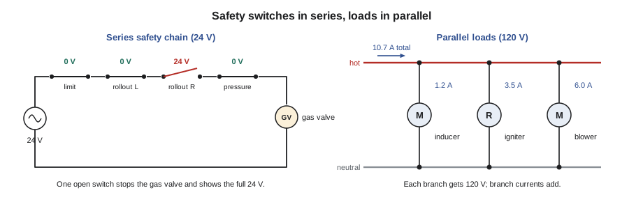
A closed switch is, ideally, a conductor with almost no resistance. An open switch is a gap with infinite resistance. That simple fact gives a gas technician one of the most useful readings there is. In a series circuit with power on, a closed switch has almost zero volts across it, because there is almost no resistance for voltage to drop across. An open switch has the full source voltage across it, because the open switch now holds all the resistance in the circuit and no current flows to cause drops anywhere else.
This is why appliance safety controls are wired in series. On a typical furnace, the 24-volt circuit to the gas valve runs through the high-limit switch, the flame rollout switches, the pressure switch and sometimes a blocked-vent switch or door switch. Each one is closed when conditions are safe. If any one opens, because the heat exchanger is too hot, flame is rolling out, the vent is blocked or the door is off, the series path is broken and the gas valve cannot be energized. One fault anywhere stops the gas. Failing safe is the whole purpose of the arrangement.
Worked problem
Finding an open safety switch
At the rental on Oakland Park Avenue, Jonah finds the furnace calling for heat with the inducer running but no ignition. The control board shows a code for an open limit circuit. With the power on, he measures across each switch in the limit circuit in turn. Suppose he reads 0.1 V across the high limit, 0.1 V across the left rollout switch, 24.3 V across the right rollout switch and 0.1 V across the pressure switch. Which switch is open?
Show solution
- Recall the rule: a closed switch shows almost zero volts, an open one shows the source voltage.
- Compare each reading with the transformer output of about 24 V:
- \[V_{\text{right rollout}} \approx V_S = 24 \text{ V}\]
- Check that the total still adds up:
- \[0.1 + 0.1 + 24.3 + 0.1 = 24.6 \text{ V}\]
Answer: The right rollout switch is open. A tripped rollout switch is a symptom, not a cause: it means flame left the burner area. Rosa reminded Jonah that it must never be jumpered or simply reset and left. The cause, which on this call turned out to be a cracked heat exchanger and a partly blocked secondary heat exchanger, had to be found and corrected first.
The parallel circuit
In a parallel circuit, components are connected side by side across the same two points, so that each has its own path, called a branch. The gas comparison is a manifold: each outlet takes gas from the same header at the same pressure, and closing one outlet does not stop the others. In a parallel circuit, one open branch does not affect the other branches.
Three rules describe a parallel circuit. First, the voltage is the same across every branch, because every branch connects to the same two points. Second, the currents add: the total current from the source is the sum of the branch currents. That is often called Kirchhoff's current law. Third, the total resistance is less than the smallest branch resistance, because every branch added gives current another way through. Adding a branch always lowers total resistance and raises total current.
For two branches only, the reciprocal formula simplifies to the product over the sum: R_T = (R₁ × R₂) ÷ (R₁ + R₂). For several equal branches, divide one branch's resistance by the number of branches: four 100 Ω branches in parallel make 25 Ω.
This is why appliance loads are wired in parallel. The inducer motor, igniter and blower of a furnace each need the full 120 volts to work properly. In parallel, each gets it, and each can be switched on and off by the control board independently. Household circuits are wired the same way: every receptacle on a circuit gets the same 120 volts, and plugging in another lamp adds current without dimming the others, until the total current reaches the breaker's limit.
Worked problem
Adding branch currents on a furnace circuit
Suppose a furnace's inducer draws 1.2 A, its igniter 3.5 A and its blower 6.0 A, all at 120 V. During ignition all three can be on at once. What total current does the furnace circuit carry, and what is the combined resistance of the three loads?
Show solution
- Add the branch currents:
- \[I_T = 1.2 + 3.5 + 6.0 = 10.7 \text{ A}\]
- Find the combined resistance with Ohm's law:
- \[R_T = \frac{V}{I_T} = \frac{120}{10.7} \approx 11.2\ \Omega\]
Answer: The circuit carries about 10.7 A at worst. On a 15-amp circuit that leaves some margin, but adding a humidifier, an electronic air cleaner and a condensate pump to the same circuit could use it up. The combined resistance, about 11.2 Ω, is lower than any single load's, as the parallel rule says.
Worked problem
Two resistances in parallel
Two heating elements of 40 Ω and 60 Ω are connected in parallel. What is their combined resistance?
Show solution
- Use the product-over-sum form for two branches:
- \[R_T = \frac{R_1 \times R_2}{R_1 + R_2} = \frac{40 \times 60}{40 + 60}\]
- Work it out:
- \[R_T = \frac{2400}{100} = 24\ \Omega\]
Answer: The combined resistance is 24 Ω, less than the smaller of the two, as it must be.
| Rule | Series circuit | Parallel circuit |
|---|---|---|
| Number of paths | One | One per branch |
| Current | The same everywhere | Branch currents add to the total |
| Voltage | Drops add to the source voltage | The same across every branch |
| Total resistance | Sum of the resistances | Less than the smallest branch |
| Effect of one open | Everything stops | Only that branch stops |
| Use on gas appliances | Safety switches, thermostat to gas valve | Loads: inducer, igniter, blower, accessories |
Series-parallel circuits
Real appliance circuits combine both. The 24-volt circuit of a furnace is a good example: the thermostat contacts and the safety switches are in series with the gas valve coil, while the gas valve, the board's own relays and the cooling contactor coil sit in parallel across the transformer. To work out a combination, take it apart into pieces you can recognize. Find any group of components that are clearly in series and replace them with their total. Find any group clearly in parallel and replace them with their combined value. Repeat until one resistance remains.
For troubleshooting, the exact arithmetic matters less than the logic. Ask two questions about every component. Is it in the path of the load that is not working, so that an open in it would stop that load? Or is it on a separate branch, so that its failure could only affect itself? A furnace whose inducer runs but whose igniter does not has a fault on the igniter's branch, or in whatever controls that branch, not in the inducer circuit or the transformer that clearly works.
Shorts and opens in each kind of circuit
An open in a series circuit stops everything, and with power on, the full source voltage appears across the open. An open in one branch of a parallel circuit stops only that branch, and the voltage across that branch's terminals at the open part still reads full source voltage, because the open part is connected straight across the supply.
A short is an unintended path of very low resistance. In a series circuit, a short across one component removes that component from the circuit: a shorted lamp goes out while the others glow brighter, because the current rises. A short across a whole parallel circuit, or across the source, gives almost zero resistance, and by Ohm's law the current rises until a fuse blows or a breaker trips. On a furnace, the most common short is a damaged thermostat cable or a pinched wire touching the cabinet, which shorts the 24-volt circuit and blows the fuse on the control board. Lesson 12 follows exactly that fault.
A ground fault is a short from a hot conductor to a grounded metal part, such as the furnace cabinet or a gas pipe. If the equipment is properly grounded, the fault current flows back through the grounding conductor and trips the breaker. If it is not, the cabinet sits at a dangerous voltage until someone touches it. Lesson 10 returns to that danger.
When a closed switch is not quite closed
The rule that a closed switch shows almost zero volts has a useful corollary. Switch contacts wear. Each time they open under load, a tiny arc burns the contact surfaces, and over years they become pitted and coated. A worn contact still closes, but it now has some resistance, and in a series circuit that resistance takes a share of the source voltage. Instead of 0.1 volt across a closed limit switch, you might read 2 or 3 volts. The gas valve downstream then receives less than its rated voltage and may open slowly, chatter or not open at all, especially on a cold morning when the transformer output is at the low end of its range.
The same thing happens at a corroded terminal, a loose spade connector or a wire nut that has come partly undone. Each is a small resistance in series with the load, and each shows up as a voltage drop where there should be none. Measuring the voltage across a closed component while the circuit is carrying current is called voltage drop testing, and it finds high-resistance faults that a resistance reading with the power off often misses, because a worn contact can read a fraction of an ohm on a meter that pushes only a tiny test current through it. Lesson 11 uses this method on a whole appliance.
Back at the shop
Hank finished the session by opening one switch on his training board without saying which. Each apprentice had to find it with the meter, power on, using voltage readings alone. Jonah found it in three readings. He started at the middle of the string, found 24 volts between the source side and that point, and kept halving the string until he was across one switch with 24 volts showing. "That's half-splitting," Hank said. "You'll see it again before Christmas."
Common mistakes
MistakeJumpering a tripped rollout or limit switch to get the heat on.
InsteadFind and fix the cause; safety switches in series are there to shut off the gas.
MistakeExpecting the same voltage across every part of a series circuit.
InsteadIn series the current is the same; the voltage divides in proportion to resistance.
MistakeThinking parallel resistance is the average of the branches.
InsteadTotal resistance in parallel is always less than the smallest branch.
MistakeAdding loads to a furnace circuit without adding up the current.
InsteadBranch currents add; check the total against the circuit's rating.
MistakeReading zero volts across a switch and calling it open.
InsteadWith power on, zero volts across a switch in series usually means it is closed; an open switch shows the source voltage.
Summary and key terms
- A series circuit has one path: current is the same everywhere, resistances add, voltage drops add to the source voltage, and one open stops everything.
- A parallel circuit gives each branch its own path: voltage is the same across every branch, branch currents add, total resistance is less than the smallest branch, and one open branch stops only itself.
- Gas appliances put safety switches in series with the gas valve so any one can stop the gas, and put loads in parallel so each gets full voltage.
- With power on, a closed switch shows almost zero volts and an open switch shows the source voltage.
- Shorts raise current and blow fuses; ground faults energize metal parts.
- Series circuit
- A circuit with one path, so the same current flows through every component.
- Parallel circuit
- A circuit in which each component has its own branch across the same two points.
- Voltage drop
- The voltage across a component caused by current flowing through its resistance.
- Branch
- One separate path in a parallel circuit.
- Ground fault
- An unintended connection between a hot conductor and a grounded metal part.
- Safety chain
- The group of safety switches wired in series with a gas valve or control.
Practice problems
Work each problem on paper first, then reveal the answer to check.
Three resistances of 10, 20 and 30 Ω are in series. What is the total?
Show answer
60 Ω.
Four 120-Ω loads are in parallel. What is the total resistance?
Show answer
120 ÷ 4 = 30 Ω.
Why are safety switches wired in series?
Show answer
So that any one opening breaks the path and stops the gas valve.
With power on, what voltage appears across an open switch in a series circuit?
Show answer
The full source voltage.
Loads of 2 A, 3 A and 5 A are in parallel. What is the total current?
Show answer
10 A.
Lesson quiz · 5 questions
Score 60% or more to complete this lesson.
Create a free account to save your progress, take quizzes and earn a certificate.