
GAS-130 · Lesson 6 of 12 · 24 min
Switches, relays and contactors
▶ Video coming soon A video version of this lesson is on the way.
After the carbon monoxide scare at Marigold Kitchen in October, Bayline had interlocked the restaurant's gas-fired make-up air unit with its kitchen exhaust hood, so that switching on the hood fans would bring on the make-up air unit automatically. On a Thursday evening in early November, the cook called: the hood fans were running, the kitchen was getting cold and stuffy, and the make-up air unit on the roof was silent. Luis took Jonah up the roof ladder with a flashlight. "The hood says run, the unit isn't hearing it," Luis said. "Somewhere between them is a relay. Let's find out which half of it quit, the coil or the contacts."
Every gas appliance is controlled by switches: some worked by hand, some by temperature or pressure, and some by a magnet. This lesson explains how switches are described, how the safety switches on gas appliances work in general terms, and how relays and contactors let a small control current switch a larger load. A later course, on appliance controls, takes the individual safety devices further.
Poles, throws and normal positions
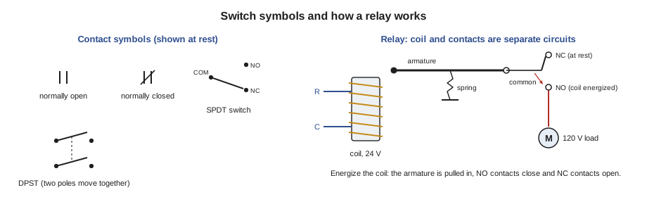
A switch makes or breaks a path for current. Switches are described by their poles and throws. The number of poles is the number of separate circuits the switch controls at once; the number of throws is the number of positions each pole can connect to. A single-pole, single-throw (SPST) switch is a simple on-off switch. A single-pole, double-throw (SPDT) switch connects one common terminal to either of two others, and is used where one condition turns one thing on and another off. A double-pole, single-throw (DPST) switch opens or closes two circuits at once, such as both hots of a 240-volt circuit. A double-pole, double-throw (DPDT) switch does both.
Contacts are also described by their normal position, which means their position when the switch is at rest, not actuated, or for a relay, when its coil is not energized. Normally open (NO) contacts are open at rest and close when the switch is actuated. Normally closed (NC) contacts are closed at rest and open when actuated. "Normal" does not mean the usual state while the appliance runs. A furnace's high-limit switch is normally closed: it is closed at rest and opens when it is heated past its setting. A pressure switch on an inducer is normally open: it is open at rest and closes when the inducer creates enough draft. That matters when reading diagrams, which always show contacts in their normal positions.
Switches worked by conditions
Many switches on gas appliances are worked not by hand but by a condition. A temperature switch, such as a high limit or a flame rollout switch, usually uses a bimetal disc: two metals that expand at different rates are bonded together, so the disc snaps from one shape to another at a set temperature and opens or closes the contacts. Some reset themselves when they cool, called automatic reset; flame rollout switches and some limits are manual reset, needing someone to press a button, precisely so that a person looks for the cause.
A pressure switch uses a diaphragm moved by air pressure or draft to close its contacts, proving that an inducer or venter motor is moving combustion products. A float switch closes or opens when water lifts a float, and is used to shut down an appliance when a condensate drain backs up. A flow switch proves water is moving through a boiler or tankless water heater. A door switch or interlock opens the circuit when a panel is removed, so the appliance cannot run with its blower compartment open. Each of these is a simple switch in electrical terms, wired in series with what it protects, as lesson 2 explained.
The meter tests for all of them follow the same pattern. With power on, measure across the switch: about zero volts means closed, full circuit voltage means open. With power off and one wire removed, measure its resistance: close to zero ohms closed, OL open. Then the real question is whether the switch is in the state it should be for the conditions, and if not, whether the switch is faulty or the condition is real. A limit that is open because the filter is blocked is doing its job.
Relays
A relay is a switch worked by an electromagnet. It has two separate parts: a coil, which becomes a magnet when current flows through it, and one or more sets of contacts, which the magnet moves. When the coil is energized, it pulls an iron armature toward it, against a spring, and the armature moves the contacts: NO contacts close and NC contacts open. When the coil is de-energized, the spring returns the contacts to their normal positions.
The great value of a relay is that its coil circuit and its contact circuit are electrically separate. A 24-volt coil circuit, fed from a thermostat, can switch 120-volt or 240-volt contacts that carry several amps. That is how a thermostat on the wall, with a few hundred milliamps of 24-volt current, can start a blower motor drawing several amps at 120 volts. It is also why relays are used to isolate one system from another, such as a furnace from a separate boiler, or a hood control panel from a make-up air unit, without tying their power supplies together.
Relays are specified by their coil voltage and coil VA or current, by their contact arrangement, such as SPDT or DPDT, and by their contact ratings: the voltage and current the contacts can switch safely. Contacts are rated differently for resistive loads and for motor loads, because motors draw a large inrush current at starting, often several times their running current, and opening an inductive load draws a bigger arc. A relay rated 10 A resistive may be rated for a much smaller motor. On modern furnaces, the relays for the inducer, igniter and blower are mounted on the control board itself. On older equipment and in commercial work, separate relays are common, often in a small enclosure called a fan center or relay panel.
Worked problem
Does the relay suit the load?
The make-up air interlock relay at Marigold Kitchen has a 24-V coil and SPDT contacts rated 10 A resistive and 1/3 hp at 120 V. It switches the 24-V call circuit of the make-up air unit's own controller, about 0.3 A, not the blower motor itself. Is it suitable, and what is the VA drawn by its coil if the coil draws 0.08 A?
Show solution
- Compare the switched current with the contact rating:
- \[0.3 \text{ A} \ll 10 \text{ A}\]
- Find the coil VA:
- \[\text{VA} = V \times I = 24 \times 0.08 \approx 1.9 \text{ VA}\]
Answer: The contacts are far larger than needed for a 0.3-A control signal, so the relay is well suited. Its coil adds only about 2 VA to the transformer that feeds it, which Luis checked against the hood panel's transformer rating.
Contactors
A contactor is a heavy-duty relay built to switch large loads, such as the compressor and outdoor fan of an air conditioner, a large blower motor, or the heating elements of an electric duct heater. It works the same way, a coil pulling contacts closed, but its contacts are larger, rated for motor loads of many amps at 240 volts or more, and usually it has one or two poles that break the hot conductors. On a residential condensing unit, the contactor coil is energized by the Y circuit from the thermostat through the furnace or air handler, so the 24-volt control system decides when the 240-volt compressor runs.
Contactor contacts wear with every start, and an arc at each opening slowly pits them. Pitted contacts have resistance, which causes a voltage drop and heat, and in time the contacts can weld closed, leaving the compressor running with no call. With power off and locked out, inspect the contacts: badly pitted, burnt or welded contacts mean the contactor should be replaced. With the unit running, a voltage reading across a closed pair of contacts should be very small; a reading of a few volts means trouble.
Worked problem
Heat at a worn contactor
A condensing unit's compressor draws 14 A. With the unit running, Jonah measures 3.0 V across one closed pole of the contactor. How much power is being lost as heat at that pole?
Show solution
- The power at the contact is the voltage across it times the current through it:
- \[P = V \times I = 3.0 \times 14 = 42 \text{ W}\]
Answer: About 42 W of heat is being released at one small contact, which explains the discolored terminal Jonah could see. The contactor needed replacing, and the compressor was receiving 3 volts less than it should on that leg.
| Device | Worked by | Typical contacts | Typical use on gas equipment |
|---|---|---|---|
| Toggle or service switch | Hand | SPST or DPST | Appliance disconnect, emergency switch |
| Limit or rollout switch | Temperature, bimetal disc | SPST NC | Stops the gas valve on overheat or rollout |
| Pressure switch | Air pressure or draft on a diaphragm | SPST NO | Proves the inducer is moving flue products |
| Float switch | Water level | SPST NC or SPDT | Shuts down on a blocked condensate drain |
| Relay | Electromagnet coil | SPDT or DPDT | Switches blower, inducer, igniter or isolates systems |
| Contactor | Electromagnet coil | One or two heavy poles, NO | Switches compressors and large motors |
Testing a relay or contactor
Testing follows the two halves of the device. Test the coil circuit first: with power on and the control calling, measure the voltage across the coil terminals. If the full coil voltage is present but the relay does not pull in, the coil or the mechanism has failed. With power off and the coil disconnected, its resistance should be within the range the manufacturer gives; OL means an open coil, and a reading near zero means a shorted coil, which will usually have blown a fuse. If no voltage reaches the coil, the fault is upstream in the control circuit.
Then test the contacts: with the coil energized, measure across the contact pair that should be closed; it should read close to zero volts if the load is connected and the contacts are closed. If it reads the full load-circuit voltage, the contacts are not closing, even though the coil is pulling in. With power off, an ohm reading across the contacts, with the relay pulled in by hand where the design allows, or by energizing the coil from a test source, confirms the same thing.
Time delays and board relays
Some switching on gas appliances is deliberately delayed. On a call for heat, the blower is not started at the moment the burner lights, because it would blow cold air into the house until the heat exchanger warms up; it waits for a set time, the blower on delay. At the end of a call, the blower runs on for a time, the blower off delay, to take the remaining heat out of the heat exchanger and protect it from overheating. Older furnaces did this with a temperature-operated fan switch on the heat exchanger. Modern furnaces do it with timers on the control board, often adjustable with small switches or jumpers, which then drive the blower relay.
The relays on a control board cannot be tested in quite the same way as a separate relay, because their coils are hidden inside the board's circuits. The practical test is at the outputs: with the board calling for a load, the board's output terminal for that load should show line voltage to neutral. If the board shows that it is calling for the inducer, the safety inputs are right, and there is no voltage at the inducer terminals, the board's relay or its driving circuit has failed. Board replacement is a last step, after every input and supply has been checked, as lesson 11 explains.
Back on the Marigold roof
On the roof, Jonah measured across the relay coil with the hood fans running: 24.4 volts. The coil was being told to pull in, and he could hear it click. Across the NO contacts that should have closed, he read 24.1 volts on the make-up air unit's call circuit: the contacts were open, or had so much resistance that they might as well be. With power off and locked out at both the hood panel and the unit, Luis pulled the relay. One contact was burnt black. Luis fitted a new relay of the same coil voltage and contact rating, and Jonah watched the make-up air unit start within seconds of the hood fans. Luis added a line to the restaurant's maintenance log asking for the interlock to be checked at every seasonal service, because a dead interlock means a kitchen running its hood fans with no make-up air: exactly the condition that caused the October call.
Common mistakes
MistakeReading "normally open" as "open while the appliance runs".
InsteadNormal means at rest, not actuated, coil not energized.
MistakeReplacing a relay with one of the same coil voltage but a smaller contact rating.
InsteadMatch coil voltage, contact arrangement and contact rating, including motor rating.
MistakeHearing a relay click and assuming the load is powered.
InsteadMeasure across the contacts; a coil can pull in while the contacts fail.
MistakeResetting a manual-reset rollout switch and leaving.
InsteadFind out why flame rolled out before resetting.
MistakeFiling pitted contactor contacts and putting the unit back in service.
InsteadReplace a contactor with badly pitted or burnt contacts.
Summary and key terms
- Switches are described by poles and throws, and contacts by their normal position, which is at rest or with the coil de-energized.
- Temperature, pressure, float, flow and door switches respond to conditions and are wired in series with what they protect.
- A relay uses a coil to move contacts; its coil and contact circuits are separate, so a 24-volt coil can switch a 120- or 240-volt load, and relays isolate systems.
- Match coil voltage, contact arrangement and contact ratings, remembering motor inrush.
- A contactor is a heavy-duty relay for compressors and large motors; its contacts pit and must be inspected.
- Test the coil circuit and the contacts separately.
- Pole
- A separate circuit controlled by a switch.
- Throw
- A position that a switch pole can connect to.
- Normally open
- Contacts that are open at rest and close when actuated or energized.
- Normally closed
- Contacts that are closed at rest and open when actuated or energized.
- Relay
- A switch worked by an electromagnet, with separate coil and contact circuits.
- Contactor
- A heavy-duty relay for switching motors and other large loads.
- Inrush current
- The high current a motor draws for a moment as it starts.
- Bimetal disc
- Two bonded metals that snap at a set temperature to work a switch.
Practice problems
Work each problem on paper first, then reveal the answer to check.
What does SPDT stand for?
Show answer
Single-pole, double-throw.
Is a furnace high limit normally open or normally closed?
Show answer
Normally closed; it opens on overheating.
A relay clicks but its load does not run. What do you measure next?
Show answer
The voltage across the contacts that should be closed.
Why are relays used to interlock two systems?
Show answer
The coil and contact circuits are separate, so the systems' supplies stay isolated.
A compressor draws 12 A and 2.5 V is measured across a closed contactor pole. How much heat is produced?
Show answer
P = 2.5 × 12 = 30 W.
Lesson quiz · 5 questions
Score 60% or more to complete this lesson.
Create a free account to save your progress, take quizzes and earn a certificate.