
GAS-130 · Lesson 4 of 12 · 24 min
Meters and safe electrical testing
▶ Video coming soon A video version of this lesson is on the way.
Two weeks into November, Priya Nair called Jonah into the office and set a box on the desk. Inside was his own digital multimeter, a clamp meter, a set of new test leads with probe covers, and a pair of safety glasses with a Bayline sticker on the arm. "These are yours now," she said. "So is the responsibility that comes with them." She opened the training record on her screen. "Before you use them on your own, Rosa signs you off on Bayline's electrical testing procedure. Live-dead-live, every time, no exceptions. Last year a technician at another shop took a shock at a rooftop unit because he trusted a non-contact tester on a dead battery. He was lucky."
This lesson covers how electricity injures people, the rules that govern testing on or near live parts, the meters a gas technician carries and how to choose and use them, and the habits that make testing safe. It does not make anyone an electrician. It makes a gas technician safe and competent with the electrical tests that appliance work demands.
How electricity injures
Electricity injures in three main ways. Electric shock happens when current passes through the body. Burns happen where current enters and leaves, and from the heat of an arc. An arc flash is an explosive release of energy when current jumps through the air between conductors, as can happen when a tool slips in a panel; it produces intense heat and light, molten metal and a pressure wave. A fourth, indirect hazard is common in the trades: a shock that is not itself serious makes someone jerk back and fall from a ladder or strike a sharp edge.
As the first lesson noted, it is the current through the body that sets the severity of a shock, and the current depends on the voltage and on the body's resistance. Dry, unbroken skin has a fairly high resistance; wet or sweaty skin, a cut, or a firm grip on a metal part lowers it sharply. University and workplace safety guidance commonly gives these rough figures for 60-Hz current from hand to foot: about 1 milliamp is barely felt; around 5 milliamps is a mild shock most people can let go of; from about 6 to 30 milliamps the shock is painful and muscle control is lost; from about 50 to 150 milliamps breathing can stop and death is possible; and at around 1,000 milliamps and above, the heart is likely to go into fibrillation. These are small currents. A 15-amp breaker will not trip at any of them, which is why a breaker protects wire, not people.
Worked problem
Why 120 volts can kill
Suppose a technician kneeling on a damp basement floor grips a faulty, energized furnace cabinet. Assume a total body resistance from hand to feet of 1,000 Ω. What current flows through the body at 120 V?
Show solution
- Use Ohm's law for current:
- \[I = \frac{V}{R} = \frac{120 \text{ V}}{1000\ \Omega} = 0.12 \text{ A}\]
- Convert to milliamps:
- \[0.12 \text{ A} \times 1000 = 120 \text{ mA}\]
Answer: About 120 mA would flow, well inside the range in which breathing can stop and death is possible, and far below anything a 15-amp breaker would notice. Ordinary household voltage is dangerous, and a damp floor makes it more so.
The rules for electrical work
In the United States, OSHA's electrical safety-related work practice rules in 29 CFR 1910 Subpart S, especially 1910.333 and 1910.335, require that live parts be de-energized before an employee works on or near them unless that would create a greater hazard or is not feasible, and that de-energized parts be locked out, tagged and tested. Construction work falls under 29 CFR 1926 Subpart K. The consensus standard NFPA 70E, Standard for Electrical Safety in the Workplace (2024 edition), sets out how employers build an electrical safety program: risk assessment, establishing an electrically safe work condition, verifying absence of voltage, and choosing protective equipment. Bayline's own procedure applies these to the work Bayline does.
Both systems rest on the same idea: the safest test is one made on a circuit you have proved dead. Testing on live circuits, which troubleshooting often requires, is a separate task with its own risk assessment, the right meter, insulated probes, protective equipment as the employer's procedure sets, and the covers kept on everything that is not being measured. At Bayline, live testing inside a furnace or boiler is limited to measuring voltage and current at the appliance's own terminals, with the appliance's cabinet doors off only as long as the test takes. Apprentices do not open service panels.
The tools
A digital multimeter (DMM) is the main tool. It measures AC and DC voltage, resistance and continuity, usually small DC currents, and often capacitance, frequency and temperature. A gas technician uses it more than any other instrument, and lesson 11 shows how. A good meter for this work has a microamp DC range for flame-signal checks, a capacitance range for motor capacitors and a temperature input for a thermocouple probe.
A clamp meter measures current by sensing the magnetic field around a conductor, so the circuit does not have to be opened. The jaws must close around one conductor only. Clamp a whole cable containing both the hot and the neutral and the two fields cancel, so the meter reads close to zero even with a large current flowing. Most clamp meters also include basic voltage and resistance functions. For small currents, such as a gas valve coil, a few turns of wire through the jaws multiply the reading, as the example below shows.
A non-contact voltage tester (NCVT), the pen-shaped tester that beeps near a live conductor, is a convenient first check but not proof that a circuit is dead. It can miss voltage on a shielded cable, through a metal box, on a conductor in a bundle, or when its battery is weak, and it can beep at induced voltage on a dead conductor. Bayline uses it to find which cable is live, never to prove one is dead. A two-pole voltage tester or a multimeter is used for that.
Meter ratings
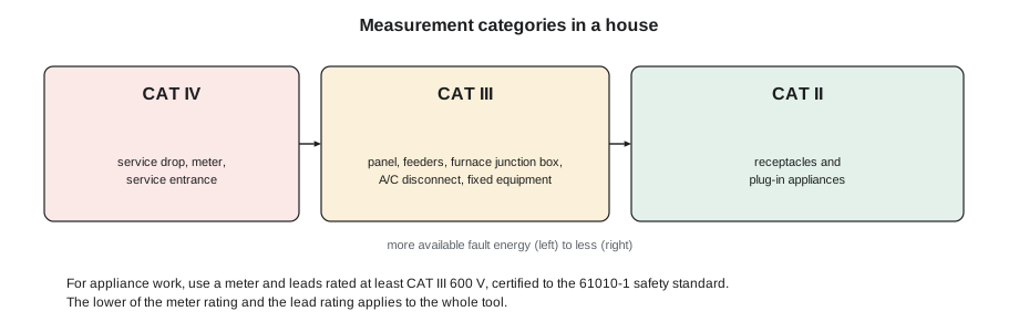
Meters are built and tested to the safety standard IEC 61010-1, published in Canada and the US as CSA C22.2 No. 61010-1 and UL 61010-1. The standard defines measurement categories according to how much fault energy is available where the meter will be used. CAT II covers receptacles and plug-in appliances. CAT III covers the distribution system inside a building: panels, feeders and permanently connected equipment such as a furnace or an air-conditioner disconnect. CAT IV covers the origin of the installation: the service drop, the meter and the service entrance. Each category is paired with a voltage, such as CAT III 600 V or CAT IV 600 V.
For gas appliance work, a meter and leads rated at least CAT III 600 V are the sensible minimum, and many technicians carry CAT III 1000 V / CAT IV 600 V meters. The rating marked on the meter applies only if the test leads carry the same or a higher rating; a CAT III meter with cheap CAT II leads is a CAT II tool. Look for the certification mark of a recognized testing laboratory on the meter, not just a CAT number printed by the seller. Check that the current inputs are protected by high-energy fuses of the type the maker specifies, and replace them only with the same type.
Before you measure
Inspect the meter and leads before each use. Look for cracks in the case, damaged insulation, exposed metal on the probes, and loose or bent connectors. Probe covers that leave only a few millimeters of metal exposed, now standard on CAT III and CAT IV leads, reduce the chance of the probe tip bridging two terminals and starting an arc. Make sure the leads are in the correct jacks for the measurement and the selector is on the correct function. The single most dangerous meter mistake is measuring voltage with a lead still in the current jack: the meter becomes a near short circuit across the supply, and only its fuse stands between the technician and an arc.
Live-dead-live: proving a circuit dead
The core test in both CSA Z462 and NFPA 70E is verifying the absence of voltage before treating a circuit as dead. The standard method, often called live-dead-live, has three steps. First, test the meter on a known live source of similar voltage, such as a receptacle or a proving unit, to show the meter works. Second, test the circuit you intend to work on, between every pair of conductors and from each conductor to ground, and confirm zero volts. Third, test the meter again on the known live source, to show it did not fail during the test. A meter that fails silently in the middle step would otherwise give a false "dead" reading.
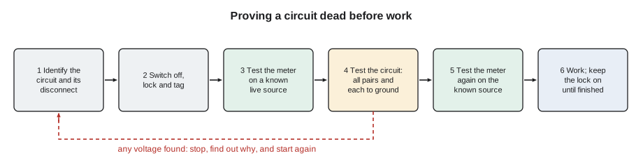
Lockout makes the live-dead-live test meaningful. Earlier training covered the lockout procedure; for electrical work on an appliance it means switching off the appliance disconnect or breaker, applying a personal lock and tag, and only then testing. On a furnace with a service switch, lock the switch off. If a switch cannot be locked, Bayline technicians use a breaker lockout device at the panel instead, fitted by someone who knows which breaker is which.
Two further facts matter on appliances. First, a furnace can have more than one source: a separate circuit for the humidifier or air cleaner, a thermostat cable from a separate transformer, or a cooling system interlocked with it. Second, the 24-volt control circuit of a furnace is fed from the furnace's own transformer, so switching off the furnace switch kills it too, but the condensing unit outside has its own 240-volt supply and its own disconnect.
Measuring voltage, current and resistance
Voltage is measured across a component or between two points, with the circuit powered. The meter's input resistance is very high, typically 10 MΩ, so it barely disturbs the circuit. That high resistance has a side effect: on a dead conductor running beside live ones, the meter can show a ghost voltage induced from its neighbors, sometimes tens of volts, that disappears under any load. Many meters have a low-impedance setting, often marked LoZ, that loads the circuit and makes ghost voltages vanish while real voltage remains.
Current is measured through a conductor. With a clamp meter, place the jaws around one conductor. With a multimeter's current range, the meter must be placed in series by opening the circuit and connecting the meter across the gap, so that all the current flows through it; this is how a microamp flame-signal reading is taken on many furnaces. Never connect a meter set for current across a voltage source.
Resistance and continuity are measured with the circuit de-energized and, where possible, the component disconnected at one end so that other paths through the circuit do not affect the reading. The meter supplies its own small test current. Measuring resistance on a live circuit gives meaningless readings and can damage the meter. Continuity mode beeps below a low resistance threshold, which is quick for checking a fuse or a switch, but it does not tell you whether a winding has the right resistance; for that, read the ohms.
Worked problem
Measuring a small current with a clamp meter
Jonah wants to check the current through a gas valve coil with his clamp meter, whose lowest range reads to 0.1 A. He wraps one of the valve leads through the jaws 10 times and the meter reads 5.2 A. What is the actual coil current?
Show solution
- Ten turns through the jaws multiply the reading by ten.
- Divide the reading by the number of turns:
- \[I = \frac{5.2 \text{ A}}{10} = 0.52 \text{ A}\]
Answer: The coil draws about 0.52 A. Wrapping turns is also how technicians measure the current in a thermostat circuit, the 24-volt current used to set the heat anticipator on older thermostats.
| Measurement | How the meter connects | Circuit state | Typical gas appliance use |
|---|---|---|---|
| AC voltage | Across two points | Powered | Supply at the junction box, 24 V at the transformer, voltage across switches |
| DC voltage | Across two points | Powered | Thermocouple or thermopile output, in millivolts |
| Current with a clamp | Jaws around one conductor | Powered | Motor amps, igniter amps, total appliance current |
| Current with the meter in series | Circuit opened, meter in the gap | Powered | Flame signal in microamps |
| Resistance | Across the part, one end disconnected | De-energized and proved dead | Igniter, gas valve coil, motor windings, thermistors |
| Continuity | Across the part | De-energized and proved dead | Fuses, switches, wiring |
Good habits
Rosa's habits, which she makes Jonah repeat until they are automatic, are worth listing. Stand on a dry surface. Keep one hand clear of the cabinet when probing live terminals where you can, so that current cannot take a path across the chest. Use probe clips or a clip lead to attach one lead before power is restored, rather than holding both probes on a live circuit. Never wear rings or a metal watch band when working inside an appliance. Read the meter, say the reading and its unit, and write it down. And if a reading does not make sense, do not touch anything until it does.
On the Friday of that week, Rosa watched Jonah carry out Bayline's procedure at a furnace: lock out the switch, live-dead-live with the multimeter at the furnace junction box, then live testing of the 24-volt circuit with the doors off and the door switch held closed with a tool made for the job. She signed the procedure sheet, and Priya filed it.
Common mistakes
MistakeUsing a non-contact tester to prove a circuit dead.
InsteadUse it to find live conductors; prove dead with a two-pole tester or multimeter using live-dead-live.
MistakeClamping a whole cable to measure current.
InsteadClamp one conductor only; the hot and neutral fields cancel.
MistakeMeasuring voltage with a lead in the current jack.
InsteadCheck lead jacks and the selector before every measurement.
MistakeMeasuring resistance with power on.
InsteadLock out, prove dead, and isolate the part first.
MistakeTrusting a CAT III meter with CAT II leads.
InsteadThe lower rating of meter and leads applies.
Summary and key terms
- Electricity injures by shock, burns and arc flash, and the current through the body sets the severity; about 50 to 150 mA can stop breathing, far below what trips a breaker.
- OSHA's Subpart S rules and NFPA 70E call for de-energizing, lockout and verifying absence of voltage before work.
- Use a meter and leads rated at least CAT III 600 V and certified to the 61010-1 standard.
- Prove circuits dead with live-dead-live.
- A non-contact tester does not prove a circuit dead.
- Measure voltage across, current through with one conductor in the clamp, and resistance with power off and the part isolated.
- Watch for ghost voltages and use LoZ where available.
- Arc flash
- An explosive release of energy when current arcs through air between conductors.
- Measurement category
- A rating such as CAT III that shows where a meter can safely be used.
- Live-dead-live
- Testing a meter on a known source, testing the circuit, then testing the meter again.
- Absence of voltage
- The verified condition that no voltage is present on any conductor of a circuit.
- Clamp meter
- A meter that measures current from the magnetic field around a conductor.
- Ghost voltage
- A false voltage reading on a dead conductor caused by coupling from nearby live conductors.
- Non-contact voltage tester
- A pen-shaped detector that senses voltage without contact; not proof of a dead circuit.
Practice problems
Work each problem on paper first, then reveal the answer to check.
What are the three steps of live-dead-live?
Show answer
Test the meter on a known live source, test the circuit, test the meter again on the known source.
Why must a clamp meter's jaws go around only one conductor?
Show answer
The fields of the hot and neutral cancel if both are inside the jaws.
What rating should a meter for appliance work have at minimum?
Show answer
CAT III 600 V, for the meter and its leads.
A clamp reads 3.6 A with a wire looped 6 times. What is the actual current?
Show answer
3.6 ÷ 6 = 0.6 A.
Why is a non-contact tester not enough to prove a circuit dead?
Show answer
It can miss voltage through shielding or with a weak battery, and gives no reading between conductors.
Lesson quiz · 5 questions
Score 60% or more to complete this lesson.
Create a free account to save your progress, take quizzes and earn a certificate.